Morrelli
Member
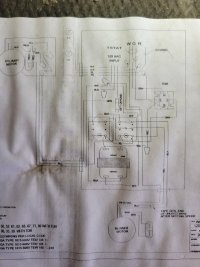
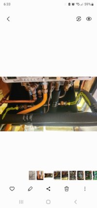
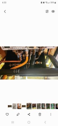
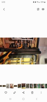
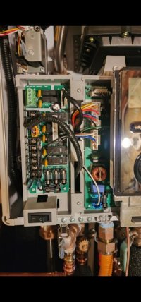
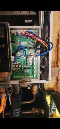
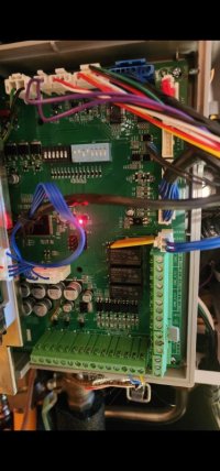
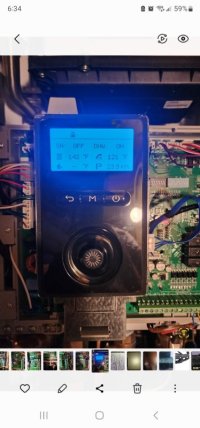
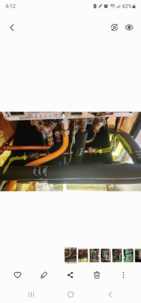
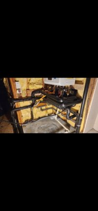
Hello all, I have posted a few times and hoping for some help. Recently had a Navien NCB 250-110H installed in place of a very old water heater that feeds two suntherm air handlers and DHW. AH model numbers and faded wiring diagram below. The combi navien has three zones, the handlers have their own pumps. The installer wired it such that the navien circulates a small loop at the unit that holds at 140 degrees and when one of the handlers calls for heat, its check valve opens, the navien senses circulation and drives temp to 180 to circulate through handler. He did not use the zone connections at the navien, instead he has a 24 volt transformer with an on/off switch for the heat side. Well, this seems a waste of propane to me. i would think each handler should be on its own zone. the navien should be more than capable to get to 180 when either handler calls for heat, not to mention having to turn a switch on and off for heat season to avoid a cycling 140 degree standby. in looking at the schematic, hoping to get a more clear one from suntherm, can anyone tell me which wires on the handlers should be connected to the zone terminals,(two conductors for each zone output), on the navien? As mentioned, the air handlers have their own pumps so having a pump running at the navien circulating a small 140 degree loop and then getting a call for heat from the handlers make me wonder if the pumps might be "fighting" eachother. Any help appreciated. I really need to make sure this is as efficient as it should be and that the controls/ navien programming are correct. Air Handler Model number:H15-52-52-A1B-CPIX-CA048A895-B2


