"Continuous" Grundfos recirculation pump stops and starts! Why??

Users who are viewing this thread

Brad Wilkinson

New Member
Messages
7
Reaction score
0
Points
1
Location
Williamson Georgia USA
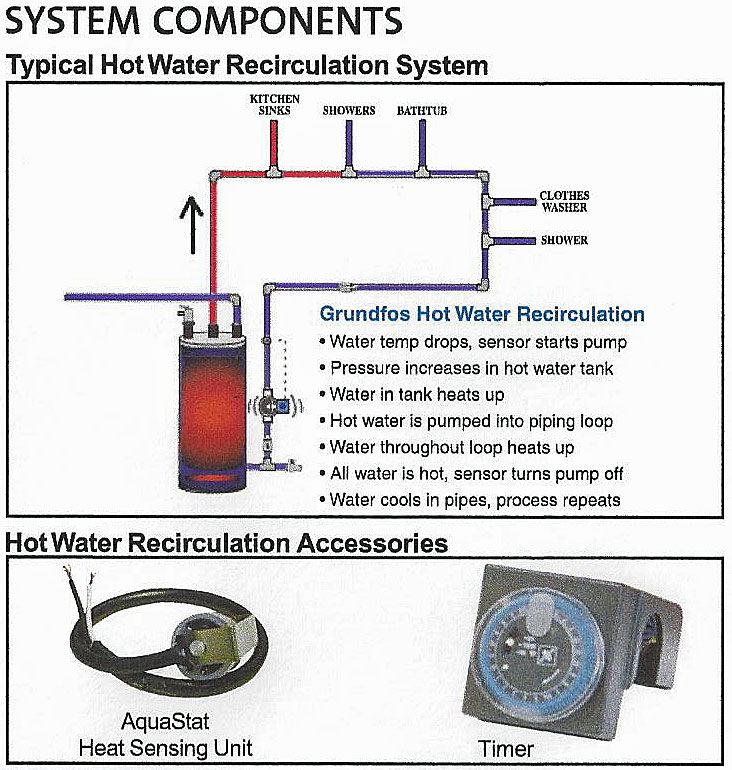
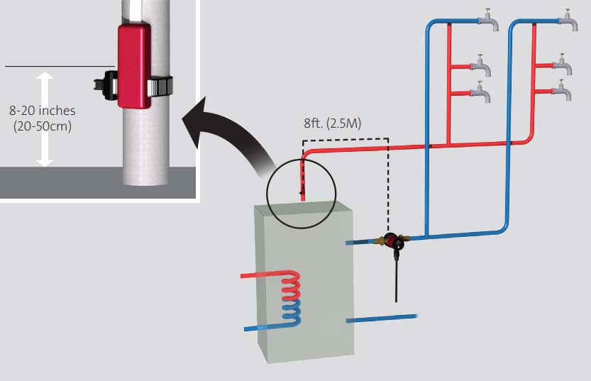
I just moved into my new house, where I got a looped hot water recirculation system installed. I had asked the plumber if he was installing a pump that would sense the water temperature and run as needed, and he said "Yes, it has a built-in temperature sensor, but they usually run all the time". So when I heard the pump stop and start regularly and constantly, I thought that was correct operation, it's about 150' round trip and I thought the water was cooling just enough in the return line to make the pump cycle some. Actually a lot, like every 5 seconds, on 2 seconds, off 3 seconds, over and over.

After spending the first night here, I noticed that all the hot water took a long time to heat up, exactly what I was trying to avoid. I thought maybe it was just that we hadn't been here and hadn't used any hot water and it was taking a while for the system to catch up. But that didn't make any sense - the recirculation loop should have hot water available at every fixture pretty quickly. Yes, some of the fixtures are several feet from the loop, and I expected a few seconds of cold water until the branch line was flushed, but it is taking minutes. The only time it is quicker is when we are using several things at once and the line is freshly hot. I have a 65 gallon heat pump water heater and it is doing fine, so it's not a supply problem at all. So this problem led me to check the recirculation pump a little closer - and it's cycling like I mentioned above - constantly.

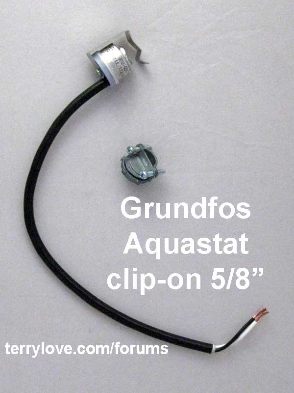
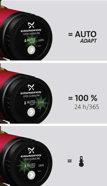
Problem is, it's not cycling because of temperature drop, it's not a temperature-sensing pump like I asked for - it's a continuous one. The one they installed is the Grundfos UP 10-16 PM "Basic" model (98420210) that is supposed to be a 100% continuous operation pump. This is not the auto-adapt A model or even the temperature-sensing T model. So that's a disappointment right there, but if it was running continuously like it's supposed to, at least I would have quick hot water supply everywhere and that's not what I have.

Does anyone have any idea why it is cycling if it is supposed to run continuously? Is there something wrong with this pump?

Thanks,
Brad
 

James Henry

In the Trades
Messages
1,579
Reaction score
404
Points
83
Location
Billings, Montana.
Can't tell you why it's cycling but I would look at the contract if you have one to see if they specified what circulating pump they were supposed to install.
 

Terry

The Plumbing Wizard
Staff member
Messages
29,942
Reaction score
3,459
Points
113
Location
Bothell, Washington
Website
terrylove.com
I sometimes install an Aquastat on the recirc line connected to the pump.
You can use with or without the timer.

grunfos_recirc_chart.jpg


grundfos_aquastat.jpg
 
Last edited:

Brad Wilkinson

New Member
Messages
7
Reaction score
0
Points
1
Location
Williamson Georgia USA
I looked at the installation a bit closer. Shouldn't the check valve be on the output (discharge, or pressure) side of the pump? Like in the drawing you provided Terry (thanks for the reply).

This one is about a foot above the pump on the suction side, not in between the pump and the water supply line to the water heater. And the check valve is cold, leading me to believe that the recirculation isn't recirculating, and no hot water is ever reaching the pump. It is an inline check valve, I assume this is a spring-loaded ball type, since it is upside down in the line and doesn't have the chamber on the side like a swing gate would.

So the pump is "sucking" on the check valve, not pushing water through it to open it. If this is the problem, like I think it is - it doesn't surprise me, the poor guy who did it didn't seem all that sharp.

And in a longish reply to James - well I didn't have a contract with plumber, he was a sub for my general contractor. And we didn't have specs - "they don't do that here", so we get what we get, which is only what they know how to do, which is only what they "have always done", not necessarily what's right. I fought subs all the way through the project, and they treated me like the typical complaining annoying homeowner. What they don't know is that I am a registered mechanical PE in the state, and I've been working on things my whole life, so I'm pretty well versed in how things work - or are supposed to anyhow. And I have the southern affliction of taking a guy's word for it when he says he knows what he's doing, trusting him to do it, and doing it on a handshake. After this project - never again. I will have specs and contracts if I ever do this again,
 

Jadnashua

Retired Defense Industry Engineer xxx
Messages
32,770
Reaction score
1,190
Points
113
Location
New England
.Make sure that the check valve is not installed backwards. As to why the pump is not staying on, follow the power to see if it goes through anything that may have a heat sensor in it. The power leads may be loose, so it could just be a poorly done wire nut or a defective solder joint. If it just plugs into the wall, plug something else into that socket and see if the power is continuous.
 

Brad Wilkinson

New Member
Messages
7
Reaction score
0
Points
1
Location
Williamson Georgia USA
hj - the pump is in-line and is between the return line and the cold water supply to the heater. There are two plastic valves; one on the incoming return line, and one on the tap into the T to the cold water supply. They put the check valve on the upstream side of the pump, just after the return valve.

It's a nice idea that they put in the two valves, so that you can shut off the system to change the pump or check valve, but there is no union to allow the threads to be separated. So the pipe will still have to be cut. It's obvious that he installed the CPVC to MIPT transitions on the pump and the check valve before he solvent-welded the CPVC together.

Also, jadnashua, the check valve is in the proper orientation, but it is ahead of the pump. The pump is plugged straight in and there is no problem with the electrical side. The pump stays on the whole time, it just stops running.

I'm pretty sure that the check valve placement is the problem. I can't find a spec for it, but since it's a 1/2" brass poppet/spring style, it probably has a cracking pressure of about 3psi. I've seen them in the 1-3psi range for this size, and the manufacturer doesn't specify it. At least without creating an account to get the tech literature. Boshart Industries 17YBCV050NL if anyone knows. So this little 6 watt Grundfos pump probably doesn't produce enough suction to crack the check valve, and then it shuts down. Maybe it has some kind of anti-cavitation protection sensing in the control. Since it is a PM inverter-drive motor, it probably has that no-load protection in its circuitry. Maybe? That would explain the intermittent shutdown/restart cycle it is in.

For now, I just unplugged it. I can either go through the hassle of calling the builder, complaining, getting him to get the plumber to come back, coordinating his visit, and then bear with him to "troubleshoot" his mistake, with the "we always do it that way, and we never have a problem" argument that I always get when I point out a problem. Or I can just buy a union for the CPVC, cut the pipe, and swap it around myself. And hope that this is the problem.
 

Jadnashua

Retired Defense Industry Engineer xxx
Messages
32,770
Reaction score
1,190
Points
113
Location
New England
There might be thermal overload for the motor, but normally, unless it's a locked rotor, it would take more than a few seconds, and maybe longer to cool off to reset itself. Might be a defective motor.
 

Terry

The Plumbing Wizard
Staff member
Messages
29,942
Reaction score
3,459
Points
113
Location
Bothell, Washington
Website
terrylove.com
Can you post a picture of what you have there? You can upload as attachments 800 pixels or less.


https://us.grundfos.com/content/dam/GPU/Products/98563206_0614_Grundfos_Comfort_US_QG.pdf

grundfos-fun-01.jpg


The pump uses two temperature sensors, one within the pump and the other connected to the pump by a cable installed in the hot-water flow pipe. The pump is installed in the hot-water return pipe.

grundfos-fun-02.jpg


UP 10-16 Comfort PM, PM Auto The UP 10-16 pump is designed for recirculation of domestic hot water in single-family homes with dedicated hot-water return piping. Utilizing a low-noise permanent magnet motor, energy consumption is reduced to as little as 5 - 8.5 W. Selecting the Auto mode ensures that the pump runs only when required. The result is maximum comfort - no waiting for hot water plus decreased water and power consumption.

Three operating modes

100 % mode
• Pump will operate 24/7/365 continuously at full speed.

Temperature mode
• Pump will keep the water temperature within an automatically detected range.

Auto mode
• Pump will learn, store and adapt operating times to home hot water consumption patterns.

Disinfection feature
• Once per week, the pump will run a 15-minute disinfection cycle.

Vacation feature
If no tappings are detected in a 24-hour period, the pump will (self-modulate) automatically switch to standby mode (except for disinfection) and reactivate to the same consumptive pattern when 2 tappings occur within a 20-minute time period.
 
Last edited:

Michael Young

In the Trades
Messages
534
Reaction score
108
Points
43
Location
North Carolina
look closely at the pump controls. You can set the controls to determine when the pump turns on. I don't like them set up for continuous. I prefer 8-minutes on/8-minutes off. Saves on wear and tear on the pump and still keeps the system charged with hot water
 

Jadnashua

Retired Defense Industry Engineer xxx
Messages
32,770
Reaction score
1,190
Points
113
Location
New England
If the temperature sensor's controller was set for the on/off temperature to be the same, it would turn on, realize it was at the set point, and turn off. On mine, the temperature difference between on/off is about 8-degrees...mine will run until the sensor sees 95-degrees, and will turn off until it drops to about 87-88. The one I have is not adjustable, but some are.
 

Brad Wilkinson

New Member
Messages
7
Reaction score
0
Points
1
Location
Williamson Georgia USA
Guys, thanks for your replies. Well, like I have already said - this is not a "controlled" pump - it doesn't have temperature sensors, temperature settings, or a motor controller that is adjustable - it is a 100% on all the time motor. But it still starts up, runs for a couple of seconds and stops, the tries again, over and over. It is a PM motor (permanent magnet) and has electronic circuitry (an inverter drive system) to drive the rotating magnetic field in the stator winding, which drives the rotor/impeller.

However, sometimes inverter-drive electronics will have some overload/no-load sensing built into their logic to protect the motor. I just don't know if this motor has those features. The Grundfos literature is pretty thin on this basic model. But, I have seen where some of their other UP line have cavitation protection, so maybe this one benefited from that tech.

I am going to try swapping the positions of the check valve and motor in the line, to see if that makes a difference. If not, it may just be a bad motor. I will keep y'all posted.
 

Brad Wilkinson

New Member
Messages
7
Reaction score
0
Points
1
Location
Williamson Georgia USA
Here's a picture of what it looks like now. Before I hack it...

IMG_20200527_174407.jpg
Line on the right is the cold water supply going down to the water heater on the right. Left side is the recirculation return line. The one across at the top is supplying an outside hose bib. The regulator and the accumulation tank is above this on the cold water supply, top right.
 

Bannerman

Well-Known Member
Messages
4,849
Reaction score
792
Points
113
Location
Ontario, Canada
Before I hack it...

How are you intending to Hack It?

Perhaps the Check valve is stuck shut so the pump is not sensing flow and is rapidly shutting down to prevent damage to the pump. You might remove the pump to test with a short section of flexible hose to draw water from and to a pan of water to verify the pump will operate continuously.

The check valve should not be located in the return loop but needs be located in the cold water supply above the location where the recirculation loop tees in. Currently, if the recirculation pump was running, the warm water being returned to the WH, can flow to cold water faucets when only cold water is being drawn.

https://images.app.goo.gl/qt7wGHacofxQnFm39

Include photos of the regulator and accumulator tank.
 
Last edited:

Brad Wilkinson

New Member
Messages
7
Reaction score
0
Points
1
Location
Williamson Georgia USA
How are you intending to Hack It?

Perhaps the Check valve is stuck shut so the pump is not sensing flow and is rapidly shutting down to prevent damage to the pump. You might remove the pump to test with a short section of flexible hose to draw water from and to a pan of water to verify the pump will operate continuously.

The check valve should not be located in the return loop but needs be located in the cold water supply above the location where the recirculation loop tees in. Currently, if the recirculation pump was running, the warm water being returned to the WH, can flow to cold water faucets when only cold water is being drawn.

https://images.app.goo.gl/qt7wGHacofxQnFm39

Include photos of the regulator and accumulator tank.

Thanks Bannerman, I am going to hack it with a hack saw... Was just a play on words really.

My plan, as I said earlier, is to swap the positions of the pump and the check valve. The check valve should be on the discharge side of the pump. Unfortunately, if I put the check valve in the cold water supply like you suggested, it will effectively cut off the expansion tank, which is just downstream of the tee that feeds the water heater. That means I would also have to relocate the expansion tank to be in the recirculation loop, so I would have excess pressure in the hot water system. Maybe that would work ok.

But what you are saying, to prevent the pump from pushing hot water back would be a problem with the system diagram that Terry had posted initially. It indicates the check valve in the line at the bottom of the tank, and that one would also push water through the tank back into the system if only cold was being used. But this logic assumes that this recirculation loop is as a higher pressure than the cold water supply. I don't really see how this pump could increase the pressure significantly anywhere else, since it is simply moving water in the loop. Sure there has to be pressure differential across the pump, but this results in lower pressure in the return line, which is what makes the water circulate in the first place. The expansion tank is absorbing the expansion of the water in the heater, and keeping the overall pressure within limits, so there is always potential for some hot water to move towards the cold side, and that's there to absorb it.

I guess what I am saying is that I don't see the benefit of putting the check valve on the supply side of the return tee. And it seems to me it would cause a bigger problem.

Here's a picture of what's above the tank. A mess of unnecessary elbows is mainly what it is. My hand is on the hot water line to the house. The first tee above the regulator is the cold supply to the water heater. This water heater doesn't have the ports on the top, they are on the side. And there is not a cold water dip tube, the cold goes to the bottom of the tank directly. Thats why the recirculation loop is tee'd in there.
Thanks!

IMG_20200530_143944.jpg
 

Brad Wilkinson

New Member
Messages
7
Reaction score
0
Points
1
Location
Williamson Georgia USA
Everyone - thanks for the replies, and the help - I appreciate it!

An update: I have fixed the problem, and the system is now working fine. The pump is running continuously, circulating the water and keeping the loop hot.

Like I said before that I was going to do, I swapped the positions of the check valve and pump, putting the pump first. To avoid a more extensive re-plumbing of what I have, I only worked between the existing shut-off valves and the CPVC-to-MIPT transition adapters. Since the plumber didn't install a union, I had to cut the CPVC to get it apart. I decided to cut it halfway between the pump and the check valve, to re-use and rearrange the parts, and I used a sharkbite straight connector/union to put them back together - minimizing repair parts in the process. The biggest problem I had was tightening the pump onto the fixed transition adapter up in the corner of the utility closet. What a poor location - I wish the arrangement was better for future maintenance.

Here's what I think is the biggest smoking gun in this problem: the guy didn't purge the return line, so the pump was trying to pump air, and wasn't priming. When I cut the line (and I used a tubing cutter BTW, not a hacksaw like I joked about) I got a little bit of spray at first break, but no big deluge after cutting through. There just wasn't any water in the line above the cut. After I got everything apart, I tested the lines to see if there was trash or anything and to flush them a bit. I just cracked the valves a bit, and I got good flow from the bottom, but several seconds of air from the top before it was steady water.

I took the pump to the bench and inspected and cleaned everything, and I tested the pump by putting a tube into a bucket of water. Once I primed the pump, it sucked the bucket down steadily. Not all that fast but steady flow. This is a small wattage pump after all. Here's the interesting bit: the pump was cycling just like it was when it was in the recirculation line, until the priming flow got to it, then it ran continuously like it's supposed to. So it appears that this Grundfos UP 10-16 Basic pump does have some no-load or anti-cavitation protection built in, even though it is the basic model intended to run continuously without the costlier temperature sensors and auto-adapting logic. Pretty cool.

When I put it all back together, I cracked the valve ahead of the pump on the return line, and flushed some water down past the check valve to make sure the pump was seeing water not air. Then I put the check valve onto the lower adapter fitting. When I plugged the pump in, it started up and ran smoothly and didn't stop at all - great! I could hear a little air bubbling through still, so I opened a few of the faucets to let the air find its way out. Now the pump is running, and it makes so little sound that you basically have to put your hand on it to tell its running. And the pipe is hot all the way through above and below the pump and check valve, so it's getting good circulation. Now it's time for some pipe insulation.

In hindsight, I guess if there had been a way to purge the loop without taking it apart, the check valve may have been OK where it was. It was really the pump running in a dry pipe that was the problem, so maybe that would have fixed it. But, I do think it's better practice to put the check valve on the pressure side of the pump, not the suction side.

Again, thanks to everyone for their help. I'm happy for now!
 

Jadnashua

Retired Defense Industry Engineer xxx
Messages
32,770
Reaction score
1,190
Points
113
Location
New England
With the lines under water pressure, it should have purged the air out on its own regardless.
 
Top
Hey, wait a minute.

This is awkward, but...

It looks like you're using an ad blocker. We get it, but (1) terrylove.com can't live without ads, and (2) ad blockers can cause issues with videos and comments. If you'd like to support the site, please allow ads.

If any particular ad is your REASON for blocking ads, please let us know. We might be able to do something about it. Thanks.
I've Disabled AdBlock    No Thanks