New 2-wire submersible pump won't start. Measures 120kohm from power to ground.

Users who are viewing this thread

macallan

New Member
Messages
7
Reaction score
0
Points
1
Location
CT
Hi I just finished installing a new replacement 2-wire submersible pump and it won't start. It's a 230v 3/4hp Red Lion pump which has a franklin electric motor.

I'm getting voltage Ok to the pump, measured at the pressure switch.

Line to Line resistance between power wires is 4ohms, measured at the pressure switch, and then at the well head. The spec sheets says this should be 3.0-3.6ohms. There's about 100 ft of wire to the pump.

A bigger issue seems to be the Line to Ground resistance, which measures about 120kohm from either power wire to ground. I measured this at the pressure switch, then I measured it at the well head by cutting the freshly spliced wires. I re-used the existing wire which looked ok as far as I could tell.

I know I should have thoroughly tested the wires and pump before dropping it in, but I didn't. Duh. Before I pull the pump again to check the wires and splices and test the new pump properly, does anyone have a good idea of what's probably wrong?

---------------------------------------

Here's an update later in the day: It turns out the pump actually does turn on and pumps, but there appears to be a clog in the output pipe to the house where I repaired a break. I might have forgotten to remove a piece of rag I used to keep dirt out. Haven't backfilled yet, thankfully.

But I'm still puzzled by the 120kohm reading from the power wires to ground. Is this normal? I thought it should be very high resistance especially on a new pump. Anyone have advice?
 
Last edited:

Reach4

Well-Known Member
Messages
40,153
Reaction score
4,724
Points
113
Location
IL
1. What is the current thru one of the hot wires? Use a clamp-around ammeter.
2. Are your splices waterproof?
 

Valveman

Cary Austin
Staff member
Messages
15,223
Reaction score
1,459
Points
113
Location
Lubbock, Texas
Website
cyclestopvalves.com
Full 230V to the motor it should do something. There should not be any short between the hot wires and the ground, but even then the pump will usually run. Ohms out ok but sounds like a broken wire.
 

macallan

New Member
Messages
7
Reaction score
0
Points
1
Location
CT
Turns out the check valve inside house wasn't opening because of iron clogging. The pump seems to work fine after replacing the check valve.

But I'm still puzzled by the 120kohm reading. Is that really ok? Shouldn't it be infinite resistance, ideally? Could this indicate degraded insulation of the old wire? If so, is that a problem that needs fixing, by pulling and rewiring the pump while I have the tools out?

Splices should be waterproof. I used crimps with waterproof shrinktube and was very careful.
 

Valveman

Cary Austin
Staff member
Messages
15,223
Reaction score
1,459
Points
113
Location
Lubbock, Texas
Website
cyclestopvalves.com
Although there should be no short to ground, I have seem pumps last many years with a big short to ground. If it is still running, get what you can out of it. Could be many more years or two days. Lol!

OH, glad you got it working. A stuck check valve can be hard to diagnose. Should only be one at the pump anyway.
 

macallan

New Member
Messages
7
Reaction score
0
Points
1
Location
CT
Although there should be no short to ground, I have seem pumps last many years with a big short to ground. If it is still running, get what you can out of it. Could be many more years or two days. Lol!

OH, glad you got it working. A stuck check valve can be hard to diagnose. Should only be one at the pump anyway.
Ok thanks.

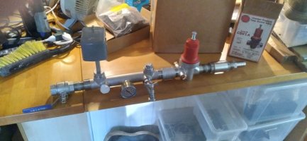
BTW I'm putting in a Cycle Stop Valve too instead of replacing the failed 34gal tank. The kit came with a check valve. Should I omit the check valve?

Another question: I'm wondering what to do with the WellMate Micronizer air injector that was installed just before the gunked up check valve, which was there as part of the iron treatment system. I'm replacing all that too but haven't designed it yet. If I eventually put the air injector back in, where should it go? Before or after the the CSV? Any other tips about this?
 

Attachments

  • csv.jpg
    csv.jpg
    58 KB · Views: 56
  • Screenshot 2024-09-19 092928.png
    Screenshot 2024-09-19 092928.png
    162.5 KB · Views: 51

Valveman

Cary Austin
Staff member
Messages
15,223
Reaction score
1,459
Points
113
Location
Lubbock, Texas
Website
cyclestopvalves.com
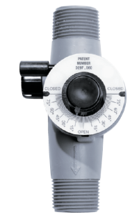
Thanks for adding the Cycle Stop Valve. You will be glad you did. But that is not one of our kits as it has a lot of unnecessary parts, including the check valve. It will work fine, just don't use the check valve.

A Micronizer adds another level of complexity. To get the Micronizer to work with a CSV a fairly large pressure tank is needed. I don't think a 34 gallon tank is large enough for a micronizer even without a CSV. I would use at least a 44 gallon size tank that holds 10 gallons of water. With a 40/60 switch setting the CSV at 58 PSI will allow full pump flow through the Micronizer and it will draw air until the tank is full to 58 PSI. At that pint the CSV goes to work and either matches pump output to the demand or restricts it to 1 GPM to finish filling the tank from 58 to 60 PSI.

There is usually not enough flow being used to make a Micronizer work when the CSV is matching demand. So the little larger tank lets the Micronizer work before the CSV does anything.
 

macallan

New Member
Messages
7
Reaction score
0
Points
1
Location
CT
Ok thanks. Is the check valve simply unnecessary, or does it actually interfere with the CSV performance?
 

Reach4

Well-Known Member
Messages
40,153
Reaction score
4,724
Points
113
Location
IL
Ok thanks. Is the check valve simply unnecessary, or does it actually interfere with the CSV performance?
It is a detriment to the system. For one thing, it can cause you to not keep your piping under pressure, so a small leak thru the yard theoretically could suck in contamination. For another, it could provide a shock as the water slams the poppet.

It does not always cause such symptoms. There are places where the above ground check valve is required, and others where such a valve is forbidden.
 
Last edited:

Bannerman

Well-Known Member
Messages
5,092
Reaction score
900
Points
113
Location
Ontario, Canada
But that is not one of our kits as it has a lot of unnecessary parts,
To clarify this statement, are you implying what is shown is a genuine CSV1A valve, but the company reselling it has either substituted the standard PK1A components, or have added components to a genuine PK1A kit?

If it is truly a genuine CSV being sold by a reseller, is the warranty support identical to those purchased directly from your company, particularly if the PK1A kit components have been either replaced or modified?
 

Valveman

Cary Austin
Staff member
Messages
15,223
Reaction score
1,459
Points
113
Location
Lubbock, Texas
Website
cyclestopvalves.com
To clarify this statement, are you implying what is shown is a genuine CSV1A valve, but the company reselling it has either substituted the standard PK1A components, or have added components to a genuine PK1A kit?

If it is truly a genuine CSV being sold by a reseller, is the warranty support identical to those purchased directly from your company, particularly if the PK1A kit components have been either replaced or modified?
Yes, it is a genuine Cycle Stop Valve. We have several resellers who purchase our valves and make their own kits. We have thousands of installers who purchase our valves and install them with whatever pump, tank, switch, combo they normally use. We encourage this and try to help our resellers and installers anyway we can. Sometimes the SS manifold and extra fittings in one of these other kits will better suit the end user. All we want is for the end user to get a real Cycle Stop Valve and be happy with their system.
 

macallan

New Member
Messages
7
Reaction score
0
Points
1
Location
CT
It is a detriment to the system. For one thing, it can cause you to not keep your piping under pressure, so a small leak thru the yard theoretically could suck in contamination. For another, it could provide a shock as the water slams the poppet.

It does not always cause such symptoms. There are places where the above ground check valve is required, and others where such a valve is forbidden.
ok got it, thanks
 

macallan

New Member
Messages
7
Reaction score
0
Points
1
Location
CT
Yes, it is a genuine Cycle Stop Valve. We have several resellers who purchase our valves and make their own kits. We have thousands of installers who purchase our valves and install them with whatever pump, tank, switch, combo they normally use. We encourage this and try to help our resellers and installers anyway we can. Sometimes the SS manifold and extra fittings in one of these other kits will better suit the end user. All we want is for the end user to get a real Cycle Stop Valve and be happy with their system.
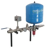
Below is a photo of the kit I have. Is it OK to install the pressure switch where shown, downstream from the CSV? The CSV install instructions specifically says not to do this, i think. But isn't the pressure going to be identical anywhere downstream from the CSV? If so, why would it matter if the switch and gauge are downstream a little? If they need to be installed on the CSV side ports I think I need to go get some extra fittings.
 

Attachments

  • CSV -manifold-amtrol-100_1.jpg
    CSV -manifold-amtrol-100_1.jpg
    152.2 KB · Views: 38
  • Screenshot 2024-09-21 093050.png
    Screenshot 2024-09-21 093050.png
    77.8 KB · Views: 42

Reach4

Well-Known Member
Messages
40,153
Reaction score
4,724
Points
113
Location
IL
The pressure switch and pressure tank must both be downstream of the CSV, and the pressure switch and pressure tank should be close to each other. The wording you marked in yellow could be better.

When water is flowing, there is always a pressure differential. You want the pressure differential between the pressure tank and pressure switch to be small. The pressure switch location in the photo you posted would be close enough, since the critical time is when the pressure switch approaches cutoff. At that time, the flow has been reduced.
 
Last edited:

macallan

New Member
Messages
7
Reaction score
0
Points
1
Location
CT
The pressure switch and pressure tank must both be downstream of the CSV, and the pressure switch and pressure tank should be close to each other. The wording you marked in yellow could be better.

When water is flowing, there is always a pressure differential. You want the pressure differential between the pressure tank and pressure switch to be small. The pressure switch location in the photo you posted would be close enough, since the critical time is when the pressure switch approaches cutoff. At that time, the flow has been reduced.
ok thanks, make sense!
 

Fitter30

Well-Known Member
Messages
4,960
Reaction score
968
Points
113
Location
Peace valley missouri
Two wire pumps have the starting components in the pump. What ever reading your getting is through starting components and length of wire. With a clamp on amp meter could tell if the pump was really running. Can purchase a cheap homeowners meter for $25 or less. If you know the depth of the pump with a pump curve can fiqure out what shut off pressure should be.
 

Valveman

Cary Austin
Staff member
Messages
15,223
Reaction score
1,459
Points
113
Location
Lubbock, Texas
Website
cyclestopvalves.com
Below is a photo of the kit I have. Is it OK to install the pressure switch where shown, downstream from the CSV? The CSV install instructions specifically says not to do this, i think. But isn't the pressure going to be identical anywhere downstream from the CSV? If so, why would it matter if the switch and gauge are downstream a little? If they need to be installed on the CSV side ports I think I need to go get some extra fittings.
It should work fine, less the check valve. But the closer the pressure switch to the pressure tank the better. As long as it doesn't bounce the pump on/off on startup the switch location will be fine.
 
Top
Hey, wait a minute.

This is awkward, but...

It looks like you're using an ad blocker. We get it, but (1) terrylove.com can't live without ads, and (2) ad blockers can cause issues with videos and comments. If you'd like to support the site, please allow ads.

If any particular ad is your REASON for blocking ads, please let us know. We might be able to do something about it. Thanks.
I've Disabled AdBlock    No Thanks