GTPlumber
New Member
Background:
We are planning to make some extra room for the master bathroom and are planning to remove the existing tub/shower combo to install instead a stand-up shower with a separate claw foot tub. I have decided to model everything in 3D instead of trying to figure it out in the crawl space. The existing drain system of the house is also ABS and I would like to stick with that. This also means that I must order my materials online as no local stores near me carry ABS anymore. This was another reason to go CAD first.
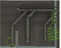
Below is the current plumbing:

(am I correct in thinking the drain for the current sink, which does have a vent stack, also vents the current toilet as a wet vent?)
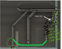
Next, the proposed new layout:


The blue wet vent shown above is the drain coming off of a sink which is dry vented up.
The larger pipes are 3" pipes, the smaller ones are 2". I may reduce the p-traps down to 1-1/2, but I'll do that later if necessary or if you guys think so.
Questions:
My questions have to do with wet venting. I will be adding one additional drain and would like to avoid adding an additional vent stack if possible. According to the international plumbing code, I know that a horizontal wet vent is allowed. I've also had many discussions with plumbers stating that a water closet needs to be the most down stream connection of a wet vented system. Here are my questions:
1. What size does the dry vent need to be before it becomes a wet vent? (My understanding of the code is that the dry vent before becoming a wet vent needs to be sized for the largest pipe it will be venting as a wet vet. In this case it needs to be able to vent the 3" pipe for the toilet.)
2. Is the capacity of the vent (how many dfu) determined by the dry vent that leads to the wet vent or only the wet vent?
Finally I'll post a larger image of what I have mocked up following a picture of what it was previously. Please feel free to critique it and point out any mistakes I may have. I am not a plumber, even though my name says that idk why I picked that, but I am just figuring this out as I go so any help would be very much welcomed.
Old (I only roughly modeled this just to get it close to what is existing so it's not exact)

New

We are planning to make some extra room for the master bathroom and are planning to remove the existing tub/shower combo to install instead a stand-up shower with a separate claw foot tub. I have decided to model everything in 3D instead of trying to figure it out in the crawl space. The existing drain system of the house is also ABS and I would like to stick with that. This also means that I must order my materials online as no local stores near me carry ABS anymore. This was another reason to go CAD first.
Below is the current plumbing:
(am I correct in thinking the drain for the current sink, which does have a vent stack, also vents the current toilet as a wet vent?)
Next, the proposed new layout:
The blue wet vent shown above is the drain coming off of a sink which is dry vented up.
The larger pipes are 3" pipes, the smaller ones are 2". I may reduce the p-traps down to 1-1/2, but I'll do that later if necessary or if you guys think so.
Questions:
My questions have to do with wet venting. I will be adding one additional drain and would like to avoid adding an additional vent stack if possible. According to the international plumbing code, I know that a horizontal wet vent is allowed. I've also had many discussions with plumbers stating that a water closet needs to be the most down stream connection of a wet vented system. Here are my questions:
1. What size does the dry vent need to be before it becomes a wet vent? (My understanding of the code is that the dry vent before becoming a wet vent needs to be sized for the largest pipe it will be venting as a wet vet. In this case it needs to be able to vent the 3" pipe for the toilet.)
2. Is the capacity of the vent (how many dfu) determined by the dry vent that leads to the wet vent or only the wet vent?
Finally I'll post a larger image of what I have mocked up following a picture of what it was previously. Please feel free to critique it and point out any mistakes I may have. I am not a plumber, even though my name says that idk why I picked that, but I am just figuring this out as I go so any help would be very much welcomed.
Old (I only roughly modeled this just to get it close to what is existing so it's not exact)
New