3-way switch replacement help

Users who are viewing this thread

turbo2pointo

New Member
Messages
3
Reaction score
0
Points
1
Location
WA, USA
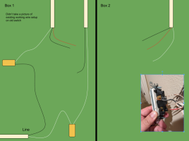
I have replaced 15 single pole switches and 1 3-way switch before. I am trying to replace another 3-way switch (Box 1), and I am confused about the wiring.
I am hoping that some of the folks can help me.

1706550891709.png


I have this multimeter if it's needed to check connectivity of the wires.
1706550691853.png
 

Attachments

  • 1706550863040.png
    1706550863040.png
    135.8 KB · Views: 28

Bgard

Member
Messages
113
Reaction score
24
Points
18
Location
NW Indiana
Box one, red and black on the 3 wire cable to traveler terminals, black from the 2 white cable to the common terminal ( different color than the two traveler terminals), box two, red and black to traveler terminals and white to the common terminal.
 

Afjes

Member
Messages
98
Reaction score
37
Points
18
Location
Northeast PA
Turbo2: A suggestion.
Next time you encounter a 3 way switch before you disconnect the existing wires from it make note and mark the wire coming off of the "common" screw on the existing switch. The "common" screw will either be a different color than the other two screws (not counting the green ground screw) or the switch will be marked at that screw location by an imprint either on the front of the switch or the back stating "common". You have to make sure that this "common" wire goes to the "common" screw on the new switch. NOTE: the new switch "common" screw location may not be in the same spot as the old switch "common" screw so be sure you attach the wire to the proper screw on the new swith. Then the other two wires are you travelers.
 

turbo2pointo

New Member
Messages
3
Reaction score
0
Points
1
Location
WA, USA
Thanks for the suggestion, folks.
I took the risk and set up box 1 as single pole switch to test my theory of the wires destinations.
Eg. attach the line to the switch, and the black from the top right to the load, and connect the neutrals as well, and it works as expected.
Once I confirm that, I rewire them as in this picture, and it works.
One thing I still haven't figure out though is why both travelers have voltage when the line is connected to ANY one of the wires that go to Box 2, even when I didn't complete the circuit or connect another other wire.
 

wwhitney

In the Trades
Messages
6,567
Reaction score
1,847
Points
113
Location
Berkeley, CA
One thing I still haven't figure out though is why both travelers have voltage when the line is connected to ANY one of the wires that go to Box 2, even when I didn't complete the circuit or connect another other wire.
A common answer is that your meter has a very high input impedance, and it can't differentiate between 120V with a conductive connection, and 120V that is present only via the capacitive coupling within the cable to a wire with 120V via a conductive connection.

I.e. most likely if you actually tried to hook a load up between a wire that reads 120V and the neutral conductor, only one of them would actually power the load. The other one would get pulled down to 0V through the load.

Commonly called "phantom" voltage.

Cheers, Wayne
 
Top
Hey, wait a minute.

This is awkward, but...

It looks like you're using an ad blocker. We get it, but (1) terrylove.com can't live without ads, and (2) ad blockers can cause issues with videos and comments. If you'd like to support the site, please allow ads.

If any particular ad is your REASON for blocking ads, please let us know. We might be able to do something about it. Thanks.
I've Disabled AdBlock    No Thanks