Help with Under Slab Rough-In Plan

Users who are viewing this thread

Still_Learning

New Member
Messages
26
Reaction score
0
Points
1
Location
Saint Louis, Missouri
Hi, all,

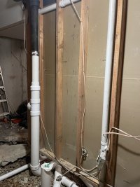
This forum has been very helpful over the years and while I mostly just read, this time I need some help. We moved into a house with a collapsed kitchen/laundry line. I excavated it and the 3" CI pipe has no bottom. I had a plumber come out and he said they could clean it out and line it, but since it's $2500 just to set up the machine, I decided to have the whole 4" CI main lateral lined at the same time. Since it's difficult to make changes after it's lined, my better half and I decided to make some changes to the 3/4 basement bathroom. So I excavated all of that and found the lines below (marked Current). The diagrams are just for the bathroom, the kitchen/laundry line is going to be lined in place and joins into the main lateral farther down.

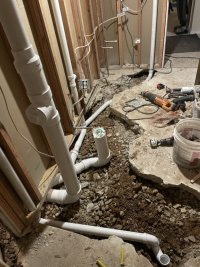
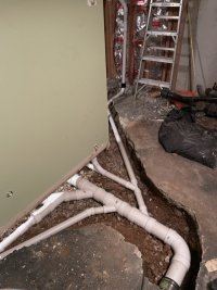
I plan to replace all the CI underground with Schedule 40 PVC, move the toilet to the right 12 inches to give it more space, and change one of the drain lines to connect in a different place so I don't have to excavate more concrete in the room beside the bathroom. This plan is marked Proposed. The Basement/1st Floor designations identify what level the drain is servicing.

Does this more or less look right? Any advice you'd give? It "seems" fairly straight forward as long as I get the slope and fittings right, but I am eager to hear any suggestions you have or pro tips for this work.

Many thanks for any help you can offer!

sewer_diagram_combined.drawio.png
 
Last edited:

wwhitney

In the Trades
Messages
6,567
Reaction score
1,847
Points
113
Location
Berkeley, CA
You refer to a basement 3/4 bath, but then your diagram only lists fixtures on the 1st and 2nd floor. So where do the basement fixtures tie in, and how are they vented?

Cheers, Wayne
 

wwhitney

In the Trades
Messages
6,567
Reaction score
1,847
Points
113
Location
Berkeley, CA
OK. So in your "current" layout you don't have any vent for the 1st floor shower (B), which is a problem. And your "proposed" layout would disrupt the way the 1st lav (E) wet vents the 1st floor WC (D).

Are you working under the IPC or the UPC?

To fix the venting for the shower you should run the its drain down the page initially, to get around the stack C coming down from the floor above, and then connect it to the lav drain, so the lav drain can wet vent it. Either before the lav drain joins the WC drain (required for the UPC), or after the lav drain joins the WC drain (only an option under the IPC). Either way the shower drain can fall at most 2", while falling at least 1/4" per foot, but the UPC further limits the run to 5' of pipe between the trap outlet and the connection to the lav drain.

If the run from the shower trap location to the lav drain can't meet those limits, your other option is to pull a dry vent off it as it passes under a wall, at a location within those limits, and then that dry vent can connect to the 1st floor lav dry vent anywhere that is at least 6" above the lav flood rim level. In this scenario, the shower drain can connect anywhere on your diagram, you only have to reroute it as required to pull the dry vent off before it joins another drain.

To avoid disrupting the 1st floor bathroom wet venting, if you want to reroute the 2nd floor drain stack (F), you need to connect it to the first floor branch only downstream of all the first floor bathroom fixtures. I.e. if you start at the first floor lav and travel downstream, you need to see the shower and the WC drains join in before you see any other drains join.

What about the kitchen sink, laundry standpipe, etc?

Cheers, Wayne
 
Last edited:

Still_Learning

New Member
Messages
26
Reaction score
0
Points
1
Location
Saint Louis, Missouri
Appreciate the help @wwhitney. I will need to think about this a little more. For some reason I was under the impression that B could be vented by A as it is currently set up.

I'm on UPC by the way. There are 4 vents that go through the roof within 10' of this bathroom so surely I can work something out.

Does this new diagram capture what you're recommending?
sewer_diagram_proposed2.drawio.png
 
Last edited:

wwhitney

In the Trades
Messages
6,567
Reaction score
1,847
Points
113
Location
Berkeley, CA
For those following along, subsequent to my responses, the diagrams in the OP were relabeled from "1st floor/2nd floor" to "basement/1st floor". So when I referred to "1st floor" in my responses, I mean what is now labeled as "basement".

For some reason I was under the impression that B could be vented by A as it is currently set up.
Not when A is carrying any drainage from the floor above.

Cheers, Wayne
 

Still_Learning

New Member
Messages
26
Reaction score
0
Points
1
Location
Saint Louis, Missouri
For those following along, subsequent to my responses, the diagrams in the OP were relabeled from "1st floor/2nd floor" to "basement/1st floor". So when I referred to "1st floor" in my responses, I mean what is now labeled as "basement".


Not when A is carrying any drainage from the floor above.

Cheers, Wayne
Assuming the new diagram is acceptable, is there any issue with that many fixtures/pipes joining in such a small area or anything else I should watch out for? I could probably run F back in it's original configuration to the main lateral and/or run the B, D, and E group over to the main lateral if it's "better". It would just mean more excavation...
 

wwhitney

In the Trades
Messages
6,567
Reaction score
1,847
Points
113
Location
Berkeley, CA
Does this new diagram capture what you're recommending?
FYI, when you edit an existing post to add new content, subscribers to the thread (such as those who have responded) don't get a notification. And if someone has responded to the post already, then it can be confusing to subsequent readers. So I suggest not editing posts other than for typos and corrections.

The new diagram has the correct connectivity order of drains. So if it complies with the distance and fall limits I mentioned and uses the correct fittings, it's good. The routing of drains in the basement bath seems a bit indirect, but perhaps you are trying to minimize slab excavation.

As for things joining in a small area, there's no problem with installing fittings back to back, and you can always use street fittings as required. When there are no competing interests, I do try to put at least one pipe diameter of exposed pipe between two hubs, mostly for ease of future modifications, which is likely less of an issue for underslab DWV.

Cheers, Wayne
 

Still_Learning

New Member
Messages
26
Reaction score
0
Points
1
Location
Saint Louis, Missouri
FYI, when you edit an existing post to add new content, subscribers to the thread (such as those who have responded) don't get a notification. And if someone has responded to the post already, then it can be confusing to subsequent readers. So I suggest not editing posts other than for typos and corrections.
My bad, will do it better in the future.

The new diagram has the correct connectivity order of drains. So if it complies with the distance and fall limits I mentioned and uses the correct fittings, it's good. The routing of drains in the basement bath seems a bit indirect, but perhaps you are trying to minimize slab excavation.
Do you mostly mean drain F? I can probably excavate to tie it in to the main where it currently is. It's not that much more work I suppose. If I did that, I'd just use two more no-hub couplings to tie in and still have the section after that lined, right?

Is there a better path for the B, D, E group that I'm not seeing?

As for things joining in a small area, there's no problem with installing fittings back to back, and you can always use street fittings as required. When there are no competing interests, I do try to put at least one pipe diameter of exposed pipe between two hubs, mostly for ease of future modifications, which is likely less of an issue for underslab DWV.

Cheers, Wayne
Good idea! I appreciate all your help!
 

Still_Learning

New Member
Messages
26
Reaction score
0
Points
1
Location
Saint Louis, Missouri
Okay, I lied. I do have another question. Does drain E need to be 4"? Couldn't it be 3" or even 2" and still adequately vent the toilet, shower, and lavatory? It's 4" CI where comes out of the slab and where the lavatory currently drains into it then transitions to 2" halfway up the wall and continues as 2" out the roof. Why would the bottom section need to be 4"?
 

wwhitney

In the Trades
Messages
6,567
Reaction score
1,847
Points
113
Location
Berkeley, CA
Drain E can be 2" as far as the wet venting rules go. Is or was there a cleanout fitting at E above the floor? Then drain was run as 4" to provide that full dimension cleanout at the end of the line of the building drain.

Cheers, Wayne
 

Still_Learning

New Member
Messages
26
Reaction score
0
Points
1
Location
Saint Louis, Missouri
Routing the basement shower between the basement lavatory and basement toilet was probably 8" over the 6-foot UPC guidance, so my new plan is to run a vent line up the wall from that shower drain (B) to tie into the E drain dry vent that goes out the roof. This is represented by the purple line in the new diagram below. Two questions:

1) Does this work and/or is it okay to tie the drain into the drain from the 1st floor shower (A) prior to joining the main?

2) Now that B is not joining into the E drain line where it was, can the F drain join in somewhere along there or does it need to join in where I have it on the diagram below?

I owe you big time @wwhitney!


sewer_diagram_proposed3.drawio.png
 

wwhitney

In the Trades
Messages
6,567
Reaction score
1,847
Points
113
Location
Berkeley, CA
0) An alternative for wet venting the shower is to reroute the lav drain to go closer to the shower.

1) That works. The shower dry vent only has to be 1-1/2", although there's something to be said for using only 2" under the slab. Use an upright (barrel horizontal, side entry vertical) 2" combo for the vent takeoff.

2) F may join anywhere not upstream of the D/E juncture (and not upstream of where the shower dry vent is pulled off, but I doubt you would have it cross over the drain from C).

Cheers, Wayne
 

Still_Learning

New Member
Messages
26
Reaction score
0
Points
1
Location
Saint Louis, Missouri
Glad this will work! I didn't think about option #0 but I think #1 will allow for a place to tie in drain F after D/E without having to run it all the way over to the main. Again, appreciate the help.
 

Still_Learning

New Member
Messages
26
Reaction score
0
Points
1
Location
Saint Louis, Missouri
This project took a little longer than expected but I’m most of the way there I think. I used clear primer and heavy duty PVC glue. I plan to test the drains multiple times before putting everything under concrete but I can say the connections from the above fixtures are running well to the main line. Pipe liner pros come next week to line the rest of the cast iron under the slab.

Does this look pretty good from what you can see in the pictures?
 

Attachments

  • IMG_5260 Large.jpeg
    IMG_5260 Large.jpeg
    82.9 KB · Views: 61
  • IMG_5254 Large.jpeg
    IMG_5254 Large.jpeg
    125.6 KB · Views: 64
  • IMG_5253 Large.jpeg
    IMG_5253 Large.jpeg
    87.9 KB · Views: 63
Top
Hey, wait a minute.

This is awkward, but...

It looks like you're using an ad blocker. We get it, but (1) terrylove.com can't live without ads, and (2) ad blockers can cause issues with videos and comments. If you'd like to support the site, please allow ads.

If any particular ad is your REASON for blocking ads, please let us know. We might be able to do something about it. Thanks.
I've Disabled AdBlock    No Thanks