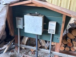
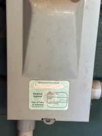
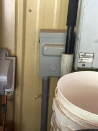
Not the pressure switch, but is the power supply for your well pump.
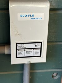
The box on the right is the submersible motor controller for an Eco-Flo pump likely equipped with a 3/4 HP motor, but take a closeup photo of the cover as it will provide clarification of the controller model code and HP rating.
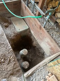
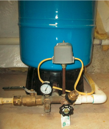
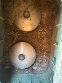
The pressure switch should appear similar to the grey box shown below, which is sensing the water pressure in the supply line directly at the pressure tank. Since it seems your pressure tank(s) is buried, your pressure switch cannot be buried and so it will need to be connected to the supply pipe and remain accessible somewhere nearby to the pressure tank location.
Edit to add: As you said your system is equipped with a CSV, where is it located? A CSV needs to be located between the pump and the pressure tank/pressure switch.