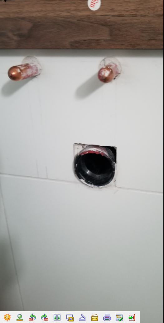
Here is what I have.
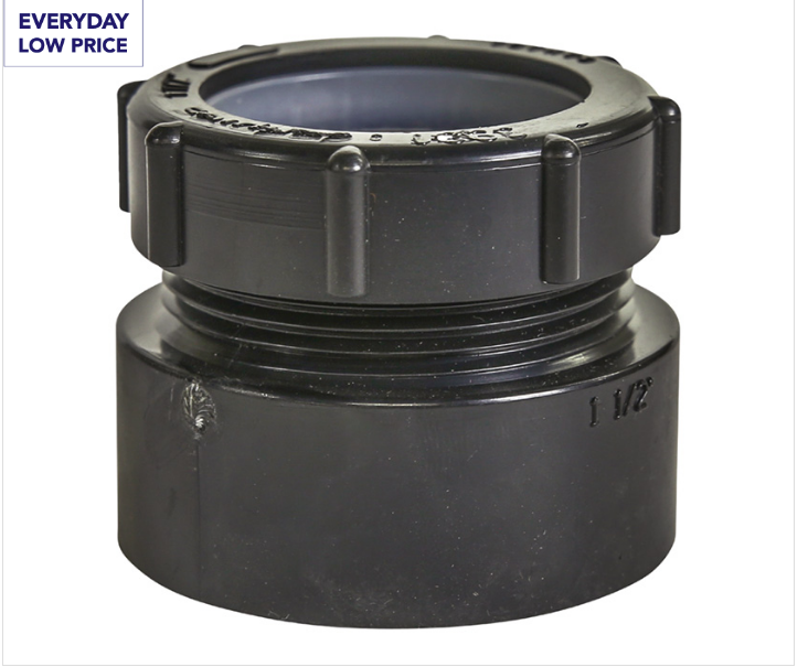
I know that I need a transition between the 1 1/4" OD grey plastic pipe and the 1 /12" ID ABS pipe (see the third picture)
One of these :
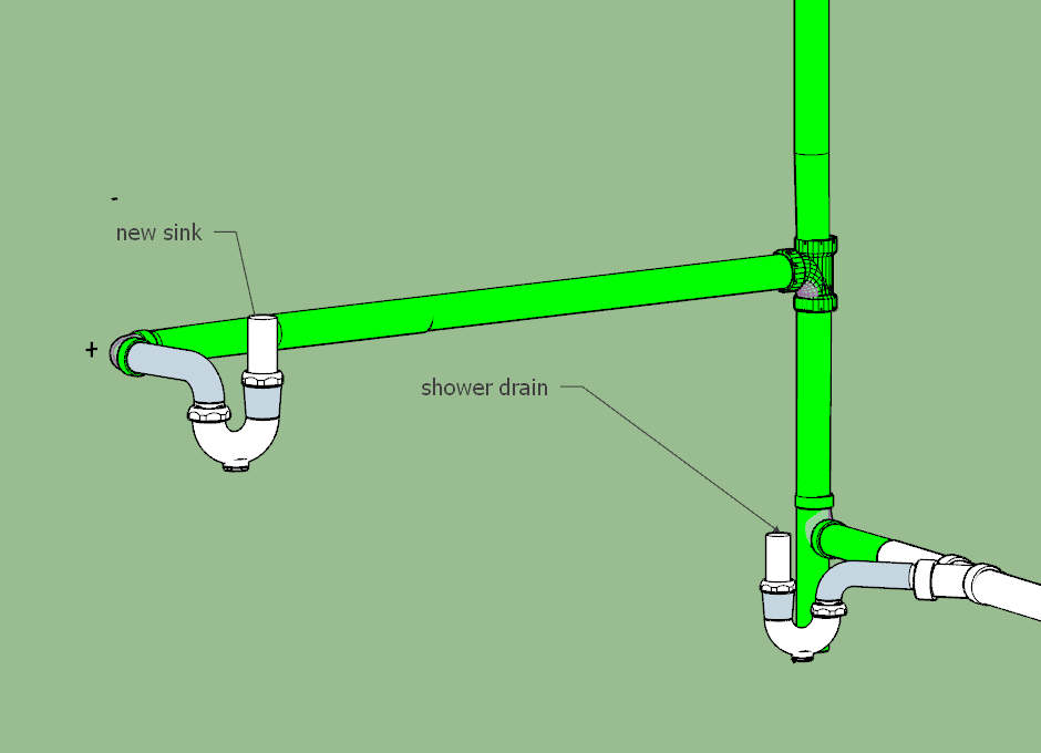
The rough in for the drain is just a 90 elbow installed horizontally (female female) like below -see the new sink plumbing; the rendering shows the idea of how the sink is vented and how that elbow, that is now out of the wall with one end, was installed.;
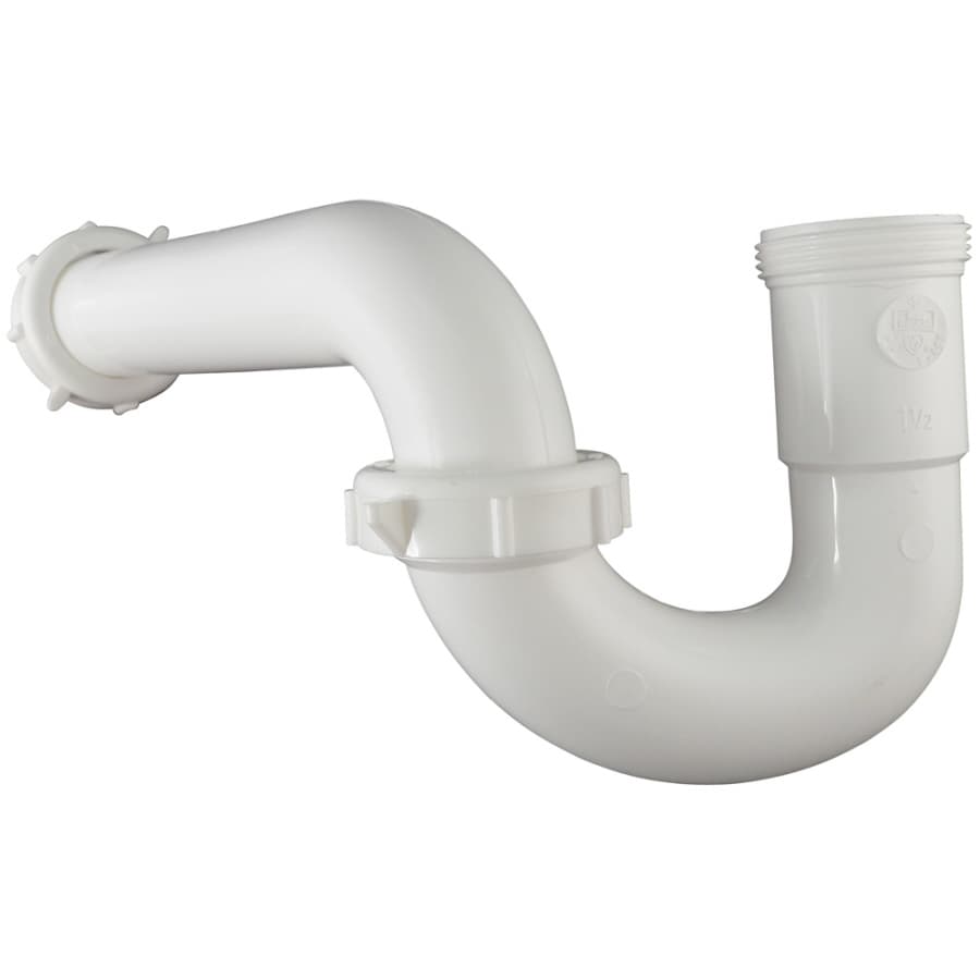
The intended plumbing under the sink looks like this
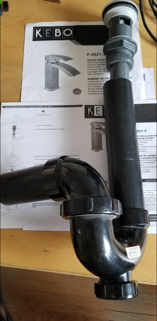
The part that I do not understand or I do not know is why is the last to the left slip nut in the below picture needed?
I am seeing that in lots of pictures on internet
I know that I need a transition between the 1 1/4" OD grey plastic pipe and the 1 /12" ID ABS pipe (see the third picture)
One of these :
The rough in for the drain is just a 90 elbow installed horizontally (female female) like below -see the new sink plumbing; the rendering shows the idea of how the sink is vented and how that elbow, that is now out of the wall with one end, was installed.;
The intended plumbing under the sink looks like this
The part that I do not understand or I do not know is why is the last to the left slip nut in the below picture needed?
I am seeing that in lots of pictures on internet