Sink PVC 90 degree turn/connection questions for vanity sink

Users who are viewing this thread

wesanc

New Member
Messages
5
Reaction score
0
Points
1
Location
Miami, Fl
Hello,
I’m new to this forum so I hope I am able to describe my questions/concerns regarding recent plumbing work done in my home.

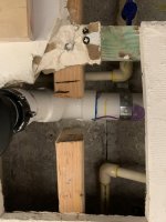
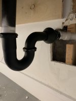
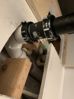
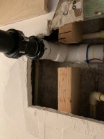
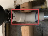
We recently had a new vanity sink and wall faucet installed. After the plumber left, I decided to turn on the faucet and immediately noticed a leak on the connection between the PVC pipe coming from the wall to the new p-trap. Plumber returned and said that the issue was with the pvc pipe on the wall, not the new connection. Seemed like an odd explanation considering that the leak was clearly coming from the new connection he made. He ended up opening my drywall, cutting the 90 degree fitting and replacing it with two new fittings and then patched up the wall. Feeling unsure of his explanation, I opened up the drywall to see the work performed and to also ensure that no leaks were occurring behind the wall. When I opened up the wall, I noticed he had installed two new fittings to turn the corner (not sure if they are correct) and also noticed that the piece that connects the pop-up drain to the p-trap is crooked.

questions:
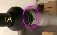
1. Are the new fittings he used to turn the corner correct?
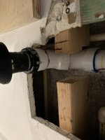
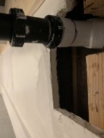
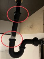
2. Is there an issue with the crooked piece between the pop up drain and the p-trap or is this a non issue?

P.S. Our new p-trap is black, so he “attempted” to paint the other pvc fittings to match so that’s why they look like that on the picture. We also noticed he cut the 2x4 to add the new fittings, so we want to make sure the new work he did it correct before we reinforce that stud.

Thanks, in advance, for your advice.

wesanc
 

Attachments

  • 3BE243B1-CFB7-4E58-9A98-AD5EBB74D03C.jpeg
    3BE243B1-CFB7-4E58-9A98-AD5EBB74D03C.jpeg
    74.9 KB · Views: 205
  • BFF1772B-9352-4B27-A906-F212769FB104.jpeg
    BFF1772B-9352-4B27-A906-F212769FB104.jpeg
    46.7 KB · Views: 206
  • F961960C-5A30-4B11-BE07-D9D1B733A84F.jpeg
    F961960C-5A30-4B11-BE07-D9D1B733A84F.jpeg
    59.8 KB · Views: 199
  • D782878D-DA3C-4CD4-8275-C65EA09790B0.jpeg
    D782878D-DA3C-4CD4-8275-C65EA09790B0.jpeg
    50.3 KB · Views: 207

Reach4

Well-Known Member
Messages
38,906
Reaction score
4,440
Points
113
Location
IL
I what is that in the magenta? Does that black at the white unscrew? I hope so.

If it does, you want to shorten the trap arm (TA) that goes into the wall. I would estimate you will take off 3/4 or 1 inch. The point is to let the trap input to be straight under tailpiece (sink output). That will take the stress off of those slip joints, which is where I think you are saying the leaks are. I am thinking you circled the leaks in https://terrylove.com/forums/index.php?attachments/d782878d-da3c-4cd4-8275-c65ea09790b0-jpeg.68488/

Ideally, the trap arm does not come out directly in line with the tailpiece, but is offset maybe 1.5 inches. That makes adjustment easier. But you have enough space where in-line will work fine.
 

Attachments

  • IMG_5.jpg
    IMG_5.jpg
    5.4 KB · Views: 187

wesanc

New Member
Messages
5
Reaction score
0
Points
1
Location
Miami, Fl
I what is that in the magenta? Does that black at the white unscrew? I hope so.

If it does, you want to shorten the trap arm (TA) that goes into the wall. I would estimate you will take off 3/4 or 1 inch. The point is to let the trap input to be straight under tailpiece (sink output). That will take the stress off of those slip joints, which is where I think you are saying the leaks are. I am thinking you circled the leaks in https://terrylove.com/forums/index.php?attachments/d782878d-da3c-4cd4-8275-c65ea09790b0-jpeg.68488/

Ideally, the trap arm does not come out directly in line with the tailpiece, but is offset maybe 1.5 inches. That makes adjustment easier. But you have enough space where in-line will work fine.


Thank you for your quick response. So the piece that was painted black that connects does unscrew. I took some additional pictures so hopefully you can get a better view. The leak was coming from this same connection.
 

Attachments

  • 1CBC1E17-A5D7-40D4-99C4-EAF697DAACA0.jpeg
    1CBC1E17-A5D7-40D4-99C4-EAF697DAACA0.jpeg
    59.2 KB · Views: 202
  • 2B1BC960-2A39-4EF2-B958-688AB7009E69.jpeg
    2B1BC960-2A39-4EF2-B958-688AB7009E69.jpeg
    69.7 KB · Views: 191
  • DEA8B1F0-1F69-44D1-B42C-69F3936D1579.jpeg
    DEA8B1F0-1F69-44D1-B42C-69F3936D1579.jpeg
    54.6 KB · Views: 205

Reach4

Well-Known Member
Messages
38,906
Reaction score
4,440
Points
113
Location
IL
Is that trap arm 1.25 inches OD, or is it 1.5 inch OD? If you don't have a caliper, consider marking a string going around the tube. Stretch out the marked string, measure between marks, and divide by pi.


You will want to get the right slip-joint washer.... 1.5 inch or 1.5 to 1.25 reducing.
green-everbilt-faucet-washers-c7197c-64_145.jpg
green-everbilt-faucet-washers-c7198c-64_145.jpg

If you will go the gittin' place before diving into the plumbing, you could buy one of each. They are cheap.

If the washer does not fix it, you will buy a matched washer and nut.
 

wesanc

New Member
Messages
5
Reaction score
0
Points
1
Location
Miami, Fl
Is that trap arm 1.25 inches OD, or is it 1.5 inch OD? If you don't have a caliper, consider marking a string going around the tube. Stretch out the marked string, measure between marks, and divide by pi.


You will want to get the right slip-joint washer.... 1.5 inch or 1.5 to 1.25 reducing.
green-everbilt-faucet-washers-c7197c-64_145.jpg
green-everbilt-faucet-washers-c7198c-64_145.jpg

If you will go the gittin' place before diving into the plumbing, you could buy one of each. They are cheap.

If the washer does not fix it, you will buy a matched washer and nut.

Thanks for your great feedback. The trap arm is 1.5.

As far the 2 fittings in the picture below, are those acceptable to make that 90 degree turn? I believe it was originally one pvc fitting with a 90 degree but the plumber changed it to the two you see in the picture. Clearly, I know nothing about plumbing so I apologize for not using the proper terminology. But, truly appreciate your feedback greatly. Just want to make all those connections are correct before we close the wall back up.
 

Attachments

  • 16D5F035-8F23-4905-B6F6-9FFD1D1B3249.jpeg
    16D5F035-8F23-4905-B6F6-9FFD1D1B3249.jpeg
    78.2 KB · Views: 185

Reach4

Well-Known Member
Messages
38,906
Reaction score
4,440
Points
113
Location
IL
As far the 2 fittings in the picture below, are those acceptable to make that 90 degree turn? I believe it was originally one pvc fitting with a 90 degree but the plumber changed it to the two you see in the picture.
Two 45s, like you have now, is better than a medium 90.
 

wesanc

New Member
Messages
5
Reaction score
0
Points
1
Location
Miami, Fl
Two 45s, like you have now, is better than a medium 90.

Awesome, phew! Feel much better knowing that. So the only thing you recommend he fixes is the crooked connection between the pop-up drain and the p-trap or is leaving it as is fine as well?
 

Attachments

  • 89110BBD-DD2A-4F46-BC9C-F14F33B5B411.jpeg
    89110BBD-DD2A-4F46-BC9C-F14F33B5B411.jpeg
    50.3 KB · Views: 185

Reach4

Well-Known Member
Messages
38,906
Reaction score
4,440
Points
113
Location
IL
Not fine. That will be fixed by shortening the trap arm.
 

Terry

The Plumbing Wizard
Staff member
Messages
29,942
Reaction score
3,459
Points
113
Location
Bothell, Washington
Website
terrylove.com
The part of the trap going to the wall needs to be cut shorter so that the vertical from the sink is straight up and down.

mission-copper-to-plastic-sink-1.jpg


I cut 2" off of this one.

At the wall there was DWV copper so a Mission copper to plastic coupling was used. I didn't really want to solder that close to the wall in an old home from the 60's.

The 90 at the wall on the question above could have been a medium 90, a long turn 90 or the two 45's.
 

wesanc

New Member
Messages
5
Reaction score
0
Points
1
Location
Miami, Fl
The part of the trap going to the wall needs to be cut shorter so that the vertical from the sink is straight up and down.


mission-copper-to-plastic-sink-1.jpg


I cut 2" off of this one.

At the wall there was DWV copper so a Mission copper to plastic coupling was used. I didn't really want to solder that close to the wall in an old home from the 60's.

The 90 at the wall on the question above could have been a medium 90, a long turn 90 or the two 45's.


Thank you so much, Terry! Glad I found this forum. Extremely helpful.
 
Top
Hey, wait a minute.

This is awkward, but...

It looks like you're using an ad blocker. We get it, but (1) terrylove.com can't live without ads, and (2) ad blockers can cause issues with videos and comments. If you'd like to support the site, please allow ads.

If any particular ad is your REASON for blocking ads, please let us know. We might be able to do something about it. Thanks.
I've Disabled AdBlock    No Thanks