Well/Pump/Cistern Electro-Hydraulic System Input

Users who are viewing this thread

Gustave

Member
Messages
43
Reaction score
1
Points
8
Location
Paso Robles, CA
Hello Forum,

I am just about done designing a system to control my well pump. I've bought all the parts, but thought I might post my design here for any inputs before I implement it. There is still time to change things.

The details are as follows:

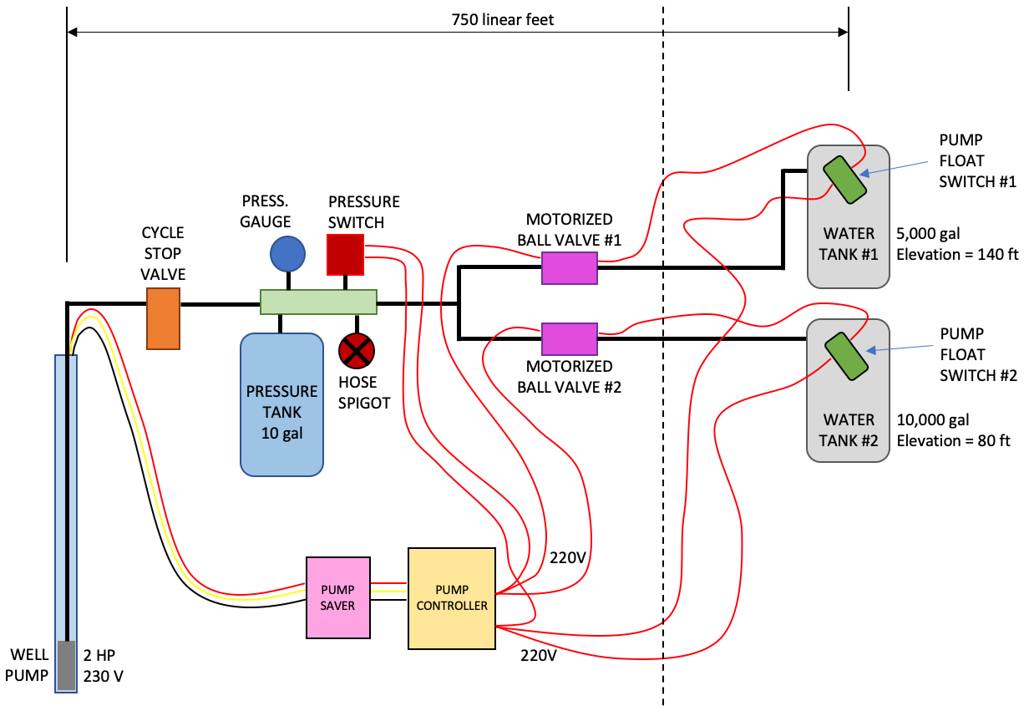
1. This is a shared well. Both my neighbor and I will use the same well.

2. I have a 10,000 gal cistern located 80 vertical feet above the well head. My neighbor has a 5,000 gal cistern located 140 vertical feet above the well head.

3. The linear distance from the well to the cisterns is roughly 700 ft in both instances.

4. I would like to be able to use water locally near the well head. Using the spigot on the manifold. Hence the pressure switch.

5. I originally planned to use solenoid valves to control the flow to the two cistern tanks. But I became concerned that they would work reliably with the residual pressure from all that elevation. So I switched to motorized ball valves. They take about 40 seconds to open or close and are powered by 230 V AC

6. I have a 1000 ft roll of 2-conductor 14 GA wire that I plan to use (inside a conduit) to allow the float switches inside the cistern tanks to turn on the pump. The original plan was to just open the motorized valves and let the pressure switch turn on the pump. But 140 ft of elevation equates to 60 psi of residual pressure. I was not sure a pressure switch would work for that.

7. The plan is to run 230V AC from the pump controller to the float switches and back. Since the current should be minimal, voltage losses should not be an issue. I think (hope?).

8. I plan to implement a pump saver and a cycle stop valve. Not sure if they are both necessary. The CSV is mostly when water is used local to the well head without a cistern.

Here is a sketch of my proposed system. If anyone has any comments I would be happy to hear them. Thank you. Gustave

Well%20Pump%20System-XL.png
 

WorthFlorida

Clinical Trail 5th session completed 4/24/24.
Messages
5,763
Solutions
1
Reaction score
998
Points
113
Location
Orlando, Florida
Running 220v power to the float switches do not seem like a good idea. You would want low voltage (24v ac). I have used this relay and its very reliable and well made. Add a 24v transformer and wire it to the float switches and the relay winding. The pump controller may already have a low voltage connection for float or pressure switches that you can use.

For 110v
https://www.functionaldevices.com/products/building-automation/details/RIBU1C/

For 220v
https://www.functionaldevices.com/products/building-automation/details/RIB2401B2G/
 

Reach4

Well-Known Member
Messages
38,903
Reaction score
4,439
Points
113
Location
IL
I would add a check valve into the path of at least the high tank.

Will the pressure switch be set to 60/80 psi, or what?
 

Gustave

Member
Messages
43
Reaction score
1
Points
8
Location
Paso Robles, CA
Running 220v power to the float switches do not seem like a good idea. You would want low voltage (24v ac). I have used this relay and its very reliable and well made. Add a 24v transformer and wire it to the float switches and the relay winding. The pump controller may already have a low voltage connection for float or pressure switches that you can use.

For 110v
https://www.functionaldevices.com/products/building-automation/details/RIBU1C/

For 220v
https://www.functionaldevices.com/products/building-automation/details/RIB2401B2G/

Thank you for that. I was sort of wondering about sending 220V way up to the tank and back just to trigger the pump.

Good tip on the relay. It's affordable and made in USA, which I always prefer. Seems silly to have to add an outside transformer and relay when the pump controller should have that built in. Mine does not (Franklin Electric).

Regarding the relay, I assume that is used simply to generate the signal for the controller right? You do not use the relay to actually turn on the pump directly?

Gustave
 

Gustave

Member
Messages
43
Reaction score
1
Points
8
Location
Paso Robles, CA
Most float switches are n.o. When float is down so you will need a relay to reverse it. Here a voltage calculator for wire size
https://www.inchcalculator.com/voltage-drop-calculator/
Thank you. I checked my float switch with a multimeter and it closes when in the "down" position. So that should be ok I think.

I am assuming that the relay coil inside the controller which turns on the pump draws very little current. In which case voltage drop should not be an issue. Is that what you are referring to?

Gustave
 

Gustave

Member
Messages
43
Reaction score
1
Points
8
Location
Paso Robles, CA
I would add a check valve into the path of at least the high tank.

Will the pressure switch be set to 60/80 psi, or what?

I thought about adding check valves, then read a bunch of negative posts about using them so decided not to.

The pressure switch is supposed to turn on the pump for local water use only, near the well head. In that case the two ball valves are closed, so when the spigot is opened the pressure will drop and turn on the pump. I plan to use a standard 40/60 pressure switch.

Gustave
 

Reach4

Well-Known Member
Messages
38,903
Reaction score
4,439
Points
113
Location
IL
Thank you. I checked my float switch with a multimeter and it closes when in the "down" position. So that should be ok I think.
In float switches, N.C. and "pump up" are two ways of saying the same thing. So you would be OK.

The float switch for a sump pump would be N.O. AKA "pump down".
 

Bannerman

Well-Known Member
Messages
4,850
Reaction score
793
Points
113
Location
Ontario, Canada
Since you are installing a pressure tank and switch, the float switches will not need to control pump operation. Use each float switch to operate the appropriate motorized ball valve only.

With both ball valves closed, the well pump will operate until the 60 psi cut-out pressure is attained. If either or both ball valves or the yard hydrant/spigot are opened, the system pressure will drop to 40 psi and the well pump will them begin to operate and continue to supply whatever valve is open at that time.

If there is a power source more local to each float switch or ball valve, electrical power for those devices may be obtained there so there will be no need to run wiring all the way back to the pump controller.
 

Reach4

Well-Known Member
Messages
38,903
Reaction score
4,439
Points
113
Location
IL
A separately-powered too-full and too-low alarm on each cistern could be a worthwhile addition.
 

Gustave

Member
Messages
43
Reaction score
1
Points
8
Location
Paso Robles, CA
Since you are installing a pressure tank and switch, the float switches will not need to control pump operation. Use each float switch to operate the appropriate motorized ball valve only.

With both ball valves closed, the well pump will operate until the 60 psi cut-out pressure is attained. If either or both ball valves or the yard hydrant/spigot are opened, the system pressure will drop to 40 psi and the well pump will them begin to operate and continue to supply whatever valve is open at that time.

If there is a power source more local to each float switch or ball valve, electrical power for those devices may be obtained there so there will be no need to run wiring all the way back to the pump controller.

Thank you. Yes, that was the original strategy. But when the ball valve for the higher tank opens, the pressure switch will "see" just over 60 psi of "back pressure" due to the 140 ft elevation of the tank. So the pump would not turn on. I would need a pressure switch that turned on at 65 psi and turned off at 85 psi, or something like that. Seemed a little squirley to me.

There has to be some signal path from the float switch to the area of the well. The distance is about 700 ft and out of sight. That rules out wireless or similar. Wires seem the most reliable.

Gustave
 

Gustave

Member
Messages
43
Reaction score
1
Points
8
Location
Paso Robles, CA
A alarm pump timer sounding a bell wired to the pump contacts might consider. If pump runs 30 minutes (adjustable) straight sounds the alarm if a motorized valve would fail open pump wouldn't shut off.
https://www.amazon.com/Timing-Delay-Switch-Module-0-100min/dp/B0755TG7MM
I do plan to have electrical power up by the tank. This would be a good consideration in case of valve stuck open. Valve stuck closed is a different story. Using the pressure switch to turn the pump on/off would solve that. Except for the elevation issue I mentioned earlier.
Thank you.
 

Reach4

Well-Known Member
Messages
38,903
Reaction score
4,439
Points
113
Location
IL
Thank you. Yes, that was the original strategy. But when the ball valve for the higher tank opens, the pressure switch will "see" just over 60 psi of "back pressure" due to the 140 ft elevation of the tank. So the pump would not turn on. I would need a pressure switch that turned on at 65 psi and turned off at 85 psi, or something like that. Seemed a little squirley to me.
I agree. 65/85 would work, but you will still want the spring-loaded check valve to the high tank.
 

Gustave

Member
Messages
43
Reaction score
1
Points
8
Location
Paso Robles, CA
I agree. 65/85 would work, but you will still want the spring-loaded check valve to the high tank.
This is an honest question. I know what a check valve is. But in this instance, what function does the check valve serve? Or what does it prevent? Thank you.
 

Reach4

Well-Known Member
Messages
38,903
Reaction score
4,439
Points
113
Location
IL
This is an honest question. What function does the check valve serve? Or what does it prevent? Thank you.
It is a one-way valve, and it prevents the top tank from dropping its water to supply the lower tank. Suppose both valves are open, and the power goes out. You don't want to drain the upper tank into the lower tank.

Suppose the pump saver shuts down the pump due to lack of water. You don't want the lower tank being filled at the expense of the upper tank during that time (if you want to be fair about it).

There is probably a case for both tanks having check valves to prevent flooding the well area if a pipe breaks, or work is being done.
 

Gustave

Member
Messages
43
Reaction score
1
Points
8
Location
Paso Robles, CA
It is a one-way valve, and it prevents the top tank from dropping its water to supply the lower tank. Suppose both valves are open, and the power goes out. You don't want to drain the upper tank into the lower tank.

Suppose the pump saver shuts down the pump due to lack of water. You don't want the lower tank being filled at the expense of the upper tank during that time (if you want to be fair about it).

There is probably a case for both tanks having check valves to prevent flooding the well area if a pipe breaks, or work is being done.

OK. You make excellent points. But why have a read so many bad stories about check valves? I would buy a good quality one, probably from McMaster-Carr.
 

Bannerman

Well-Known Member
Messages
4,850
Reaction score
793
Points
113
Location
Ontario, Canada
If the water enters each cistern above each cistern's highest water level (preferred), the upper tank will not drain-back to the lower tank.

Assuming the motorized ball valve actuators will be spring-loaded to close when there is no power, because the ball valves are slow closing, there is potential for the water in the feedline to the higher elevation tank to drain back into the lower tank during an initial loss of power.

This is also likely to occur if both motorized ball valves are open at the same time as the flow into the lower cistern will probably consume all of the flow from the pump so most of the water within the supply line to the upper tank will drain back into the lower tank.

Because you are planning to utilize a CSV, even if the well pump is activated by the cistern float switches, the system pressure will need to be higher regardless.

For a 40/60 PSI system, a CSV will be typically calibrated to regulate flow at about 50 PSI+-. Because the CSV will continually sense ~60 PSI backpressure from the supply line running up to the 140' cistern when MBV#1 is open, then the CSV will not open to regulate the flow rate so it will only allow 1 GPM to pass through.

To increase the flow rate through the CSV, the system pressure settings will need to be higher than the backpressure. A 65/85 pressure setting will permit the CSV to be calibrated for 75 psi. The CSV will then be fully closed (1 GPM flow) only when the 'downstream' pressure is 75 psi or above.
 
Last edited:

WorthFlorida

Clinical Trail 5th session completed 4/24/24.
Messages
5,763
Solutions
1
Reaction score
998
Points
113
Location
Orlando, Florida
Thank you. Yes, that was the original strategy. But when the ball valve for the higher tank opens, the pressure switch will "see" just over 60 psi of "back pressure" due to the 140 ft elevation of the tank. So the pump would not turn on. I would need a pressure switch that turned on at 65 psi and turned off at 85 psi, or something like that. Seemed a little squirrely to me.

There has to be some signal path from the float switch to the area of the well. The distance is about 700 ft and out of sight. That rules out wireless or similar. Wires seem the most reliable.

Gustave

Do as Reach suggest, put in a check valve between the tank and ball valve. So when the bottom tank or home calls for water, the pressure from the higher tank will not impact the pressure switch. It won't work any other way. You should also add a check valve at the lower tank just to prevent any back flow such as when a spigot is open near the pressure tank. Maybe backflow preventers would be more prudent.

700+ feet is very long for a 24v to travel. Besure to get a larger unit than a doorbell size. The relay works with a switch and 24v AC is applied to the coil side. What you put on the contacts is up to you. Yes, you can switch on a motor with this relay or put 5 volts on it and use it as a signal. On the relay label it gives the contact voltage and amperage ratings.
 
Top
Hey, wait a minute.

This is awkward, but...

It looks like you're using an ad blocker. We get it, but (1) terrylove.com can't live without ads, and (2) ad blockers can cause issues with videos and comments. If you'd like to support the site, please allow ads.

If any particular ad is your REASON for blocking ads, please let us know. We might be able to do something about it. Thanks.
I've Disabled AdBlock    No Thanks