Lastly, could someone explain to me exactly how changing the phase resulted in a decrease in voltage? Were/are my transformers essentially wired in series, so that when the 2 ac currents are out of phase, the max amplitude of the sine wave (and therefore voltage) is equal to only one xformer's output, and when they're in phase, the waves stack on top of each other and become additive? And would switching the breakers to different legs on the main electrical panel have the same effect?
I don't know how your transformers are wired. The Honeywell link does not work for me. The best description of how a typical thermostat works, that I have found, is "Thermostatic Wiring Principles: by Bob Scaringe Ph.D., P.E.
http://www.epatest.com/store/resources/images/misc/how-a-thermostat-operates.pdf
Let's assume your original system was wired as shown on page 8.

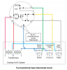
This is slightly modified version of the page 8 schematic.
The thermostat's job is to connect either the Rc or Rh, as appropriate, to whatever is being controlled, or to provide an open circuit to turn the thing off. The thing being controlled , such as a relay, would be connected between the controlled terminal and C. Thus power provided = on. Open provided = off.
The two transformers in the page 8 2-transformer situation don't have either terminal of either transformer connected together.
In your thermostat, there is only an R terminal. Now the thermostat cannot provide power from the just the appropriate supply. Instead it can only provide power from the one terminal, if I understood the discussions here. I think that Rh and Rc could be connected to R since the non R legs of the transformer are not connected together.
Transformers should not normally have secondary windings in parallel. So connecting two transformers to a single R terminal and also connecting the other side of each transformer to a C terminal would be bad.
Suppose Rh and RC are connected together in your situation. Let's call the other secondary lead of the transformer that connects to Rh to be Ch. Let's call the other transformer's C line Cc.
Anyway, are transformer secondaries that have one wire in common in series? You could think of them that way. But since there is no real load AFAIK that is between Ch and Cc, there doesn't seem to be a reason to consider them to be in series or not.
That is until you put your voltmeter where you put it. Now you see the effects of the transformers, for this purpose, being in series. Depending on the phase, you will see more or less voltage between the terminals that you are measuring between. Yet that voltage is only academic.
If you reverse the primary lines on one transformer, you should get the same effect as reversing the secondary lines on that transformer. The phase changes. So yes, if you wire one of the transformers to a different side of the AC line, the phase changes.
To see a description of how you can get less voltage from two transformers in series, look up "bucking transformer". In an example of a typical case, a 120 vac transformer is put in series with a 12 vac transformer. Depending on how the wires are phased, you get 132 (boost) or 108 vac (buck).
So yes the voltages add, but they add as vectors or complex numbers. When we say 120 vac, that is only the magnitude, and magnitude is sufficient for most purposes. For computing the effects of combining voltage sources in AC, we need to include the phase in the math.
In the kind of thing you are doing here, considering only 0 degrees and 180 degrees is enough for most simple calculations. You can make a simple model by thinking of a 120 volt DC battery in series with a 12 volt battery. In 3-phase, it gets harder. The supply voltages are 120 degrees apart; the battery analogies don't work in that case.