Pressure Pump Cuts In and Out at 60 psi

Users who are viewing this thread

WOP31

New Member
Messages
5
Reaction score
0
Points
1
Location
Odon Indiana
Hello all, and thanks for having me. I have done some poking around and found some good info on the forums but have not been able to find anyone with the same issue that I am having.

I have just redone my cistern set up in my basement and having an issue with my pump. It will build pressure and it cuts out at 60 psi, as it should. But when it cuts out the pump acts like it loses pressure, then cuts on again, then off, then on then off, etc.... It will then repeatedly cut in and out as it "Bounces" off of 60psi. All testing has been done with the valve from the pump/accumulator to the house closed, so I am only pressurizing the accumulator tank. The house is currently running on just city pressure as the tank/pump is bypassed.

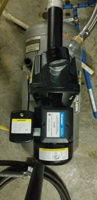
I have included a picture of my set-up. On the advice of a plumber friend, I am going to add a valve on the output of the accumulator tank so that it can be isolated.

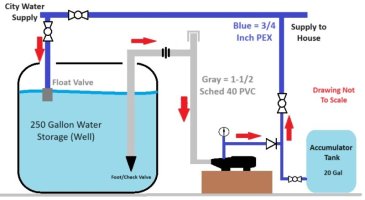
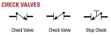
Aside from adding in a valve at the accumulator and adding the check valve on the output of the pump the system is the same as was previously there.

NOTE: The reason for this set up is that the city water supply pressure is very low, and it is unable to supply the volume drawn by the pump, so the previous owner put the cistern tank in the basement.


Pressure Pump Diagram.jpg
 

Reach4

Well-Known Member
Messages
38,907
Reaction score
4,440
Points
113
Location
IL
If you can relocate the pressure switch to the input of the pressure tank (labeled accumulator tank) then that should cure the premature cut-off. Is that black diode symbol, above and to the right of the pump, representing a check valve, or what?

Alternatively, unscrew the pressure sense line from the pump housing, plug that hole, and extend the pressure sense over to the input of the pressure tank.
 

WOP31

New Member
Messages
5
Reaction score
0
Points
1
Location
Odon Indiana
If you can relocate the pressure switch to the input of the pressure tank (labeled accumulator tank) then that should cure the premature cut-off. Is that black diode symbol, above and to the right of the pump, representing a check valve, or what?

Alternatively, unscrew the pressure sense line from the pump housing, plug that hole, and extend the pressure sense over to the input of the pressure tank.


Yes that is a check valve, I tried to use some of the actual schematic symbols, at least what I could find online. I am not an expert at plumbing but have a good knowledge of schematics, I am an electronics tech by trade. But all of my experience has been on military aircraft and surveillance systems. So I am slightly out of my element when it comes to residential plumbing.

The pressure switch is a part of the pressure pump, so I am not sure how I would move it. I have attached a top down picture of the pump so you can see where the switch is located. Disregard the gray tank under the pump, it is only there to mount the pump to. The previous owner installed a new accumulator tank and used the old one as a pump mount since it is bolted to the floor.

Any advice on how to relocate the switch port would be great. Thanks
 

Attachments

  • 20240407_184206.jpg
    20240407_184206.jpg
    60.1 KB · Views: 20

WOP31

New Member
Messages
5
Reaction score
0
Points
1
Location
Odon Indiana
If you can relocate the pressure switch to the input of the pressure tank (labeled accumulator tank) then that should cure the premature cut-off. Is that black diode symbol, above and to the right of the pump, representing a check valve, or what?

Alternatively, unscrew the pressure sense line from the pump housing, plug that hole, and extend the pressure sense over to the input of the pressure tank.


I now see the second line of your post explains how to relocate it. I guess I'll have to wait till Tuesday as everything around here will be closed tomorrow because it's going to get dark for 4 minutes in the afternoon. I guess that calls for an entire day off.

Thank you. I will try relocating it and let you know if that help.

Any idea on why it is doing that? I am weird and like to know how and why things work like they do.

Thank you.
 

WOP31

New Member
Messages
5
Reaction score
0
Points
1
Location
Odon Indiana
Remove the check valve between the pump and the tank.
That was another thought that I had, since it is the only difference to how it was set up previously. But from what I was reading on some posts on this forum, people were recommending it be there.

That seems like an easier test just to see if it fixes the issue. If that is the issue, then relocating the pressure switch line would then make sense too.

Thank you.
 

Bannerman

Well-Known Member
Messages
4,850
Reaction score
793
Points
113
Location
Ontario, Canada
In addition the the prior recommendations:

1) What is the pressure tank's air pre-charge pressure?

The air pre-charge is to be tested using a tire pressure gauge on the tank's Schrader valve after the pump is de-energized, and after the pressure tank is completely drained of water.

2) What is the brand and model of pump?

3) What is the pressure switch Cut-In setting? So far, you have stated the Cut-Out setting is 60 psi.

4) Is there actually a 'Foot Valve' within the cistern? A foot valve incorporates a check-valve so an additional check valve is unnecessary and often creates problems.

5) What is the water pressure directly from the city supply?

6) Your diagram shows the piping from the pump to the pressure tank as smaller diameter than anywhere else. What is the diameter of that pipe?
 

WOP31

New Member
Messages
5
Reaction score
0
Points
1
Location
Odon Indiana
In addition the the prior recommendations:

1) What is the pressure tank's air pre-charge pressure?

The air pre-charge is to be tested using a tire pressure gauge on the tank's Schrader valve after the pump is de-energized, and after the pressure tank is completely drained of water.

2) What is the brand and model of pump?

3) What is the pressure switch Cut-In setting? So far, you have stated the Cut-Out setting is 60 psi.

4) Is there actually a 'Foot Valve' within the cistern? A foot valve incorporates a check-valve so an additional check valve is unnecessary and often creates problems.

5) What is the water pressure directly from the city supply?

6) Your diagram shows the piping from the pump to the pressure tank as smaller diameter than anywhere else. What is the diameter of that pipe?

Thank you for your reply.

1) This is where I am still in my learning curve as a novice plumber. I have not checked the pressure in the accumulator tank as of yet. One of those things that I didn't know that I needed to know. It is on my list of items to check first thing tomorrow.

2) LEO - UDPM75-1

3) Factory settings say 40/60

4) Yes, an actual foot valve. It didn't appear to have anything wrong with it on visual inspection prior to install.

5) I am not sure of exactly what the city water pressure is. Best estimate is 20-25-ish PSI. Maybe more if the standpipe down the road is full. I live in a very very rural area.

6) I have updated my diagram. All Blue lines are 3/4" PEX, and all Gray lines are 1-1/2" Sched 40 PVC. I have limited SW available on my personal computer for making diagrams, so I am limited in my drawing capacities.

Thank you for all the input. I will be checking my tank pressure in the morning and making a trip to the hardware store when I can to try and relocate the switch trigger line.
 

Attachments

  • Pressure Pump Diagram.jpg
    Pressure Pump Diagram.jpg
    43.2 KB · Views: 24

Valveman

Cary Austin
Staff member
Messages
14,638
Reaction score
1,304
Points
113
Location
Lubbock, Texas
Website
cyclestopvalves.com
As was said, remove the check valve after the pump. The foot valve is the only check valve needed. But it would still be best to add another pressure switch close to the tank. You can just wire around the existing switch and not have to remove it. You can see a wiring diagram of how to do that here under "jet pumps". It would also be good to add a Cycle Stop Valve to stop the pump from cycling and deliver strong constant pressure to the house.

wiring diagram.jpg


Reach4

Well-Known Member
Messages
38,907
Reaction score
4,440
Points
113
Location
IL
Yes that is a check valve, I tried to use some of the actual schematic symbols, at least what I could find online.
Edit: I now remembered that is a stop valve symbol just above the right-most red arrow.
 
Last edited:
Top
Hey, wait a minute.

This is awkward, but...

It looks like you're using an ad blocker. We get it, but (1) terrylove.com can't live without ads, and (2) ad blockers can cause issues with videos and comments. If you'd like to support the site, please allow ads.

If any particular ad is your REASON for blocking ads, please let us know. We might be able to do something about it. Thanks.
I've Disabled AdBlock    No Thanks