Can loose connections overload a fuse?

Users who are viewing this thread

Leejosepho

DIY scratch-pad engineer
Messages
2,483
Reaction score
0
Points
36
Location
200 miles south of Little Rock
Website
www.nonameyet.org
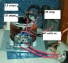
You should be shooting for about 56 V ...

Since I know there are people who believe, for whatever reasons, you should not be helping me here – peace to all – maybe I should explain how I arrived at 70 volts for the piece of wire I have embedded in my bathroom floor. And of course, I will quickly reconsider my own computations if anyone can show me a better or more correct way to make some. In spite of how anybody else might ever approach telling somebody else how to heat or how not to heat any floor electrically, this is not an off-the-shelf situation and I must deal with the mechanical realities of whatever I actually have.

The mat I purchased was advertised as being 3’ X 20’, and it arrived in an EasyHeat box with this on the label:

SEC-8-20X36
15 Watts per SqFt
900 Watts Total – 208 Volts

However, I actually received a 3’ X 30’ mat with no label or specs of any kind, the seller did not have any further information available and EasyHeat did not respond to any of my several e-mails. So, I next began trying to learn whatever I needed to know so I would not end up burning down my house.

The mat I received covered 90 sq. ft., and that would amount to a total of 1350 watts *if* 15 watts per sq. ft. is correct for it. However, 50.1 ohms and 208 volts translate into a total of 864 watts rather than 1350 (90*15), and that low number would break down to a mere 9.6 watts per sq. ft. for a heating mat in a concrete floor ... and it has just now struck me that possibly that mat was intended for clearing a sidewalk rather than for heating a floor in a living space.

Question: Does anyone know what wattages are used for melting snow and ice on walkways and driveways or the like?

Knowing what it takes to get my floor above room temperature even when it is already relatively warm, I cannot imagine 9.6 watts melting ice from a frozen sidewalk in an ambient temperature well below freezing. But, maybe that assumption is wrong.

All considered, here are the computations I have used so far:

Original piece
3' x 30' mat = 90 sq ft
90*15=1350 watts total
50 ohms and 1350 watts coincide with 260 volts and 5.2 amps

Knowing 260 is a funny voltage, I next assumed the mat might be meant for 240 volts rather than 208, and with the wattage discrepancy amounting to some kind of safety factor related to its no-burn maximums. At that point, I began a great amount of careful and comprehensive testing before actually installing any wire anywhere, and I have since become convinced the following *maximums* are completely safe:

14-ohm cut piece installed in main-floor bath
14/50=.28 of original total
.28*1350=378 watts @ 72.75 volts @ 5.2 amps

24-ohm piece headed for one end of workshop
24/50=.48 of original total
.48*1350=648 watts @ 124.7 volts @ 5.2 amps

9-ohm piece headed for 2nd bath
9/50=.18 of original total
.18*1350=243 watts @ 46.77 volts @ 5.2 amps

Some of my recent posts show some different numbers where I had not first gone back and looked at my notes and such, but 70 is less that 72.75 and so on.

Thank you, Terry, for such a great place where I can continue to listen and learn while DIYing and still keeping my house in livable condition!
 
Last edited:

Leejosepho

DIY scratch-pad engineer
Messages
2,483
Reaction score
0
Points
36
Location
200 miles south of Little Rock
Website
www.nonameyet.org
The heating cable is designed for 4 A RMS. That should be your target from the controller.

Payne has given me an RMA number for sending the controller to be checked and possibly repaired, and I am still trying to be sure I am dealing with this heating wire correctly and safely.

I do not have any technical knowledge of exactly what "4 A RMS" means, but logic suggests that number should be considered in place of the "5.2 amps" in my own calculations. With that in mind:

The label on the box said 900 watts total at 15 per sq. ft. and 208 volts. Doing the math, I get this:

900/208=4.33 amps.

If I am understanding correctly, that is "4 A RMS".

But if I apply that same rating to my larger mat as 1350 watts as it was, I get this:

1350/208=6.49

Am I missing something when I conclude my wire must be rated for some amperage greater than 4?

Or, maybe you were thinking of the 900-watt piece?
 

Leejosepho

DIY scratch-pad engineer
Messages
2,483
Reaction score
0
Points
36
Location
200 miles south of Little Rock
Website
www.nonameyet.org
A 1000 Watt dimmer would work and they are available on-line for around $50. http://www.prolighting.com/luglglprsipo1.html

I would put a stop on it, and probably a fuse, because putting 120 Volts on a heating circuit designed for 70 Volts would nearly triple the heat output.

Whether I end up with the controller or a dimmer, would you have any suggestions as to what kind or type of fuse?

Yesterday I finally found a couple of congenial folks at the third local local supply house I have visited where I bought some fast-acting (no time delay) 5-amp fuses to see where they would actually blow, and I gave after 3 long seconds at 8 amps!
 

Alternety

Like an engineer
Messages
768
Reaction score
0
Points
16
Location
Washington
I believe you said the whole mat was about 50 ohms and designed for 208 V. E=IR thus I=E/R thus 208/50 = 4.16 A That is the design current of the whole mat. No subset of any size should be made to run at a different current.

RMS is root mean square (there, isn't that better now). Basically the true average of the area under the curve of the waveform. When talking about power to a resistive load it is the "real power".

Use this current in all your arithmetic. 14 ohm cable - E=IR 4.16*14= 58.2 V source. P = EI = I sq * R = 220W

In this case, watts are advertising. voltage across measured resistance = real.

The question you really want answered from Payne is this - What is the minimum resistive load that can be attached without blowing the very fast acting fuse when the output voltage is full on?

The schematic you sues is interesting. It really does feel old. They have three opto-isolated SSRs (Solid State Relays) in series with resistors across them to equalize the voltage across each (like when you have to use diodes is series to make a total voltage rating.

Single SSRs are available that do this. This is an example of such a device: http://www.newark.com/18M9337/elect...TYCO-ELECTRONICS-POTTER-BRUMFIELD-SSRT-240A10

Understand I am not suggesting you simply use this device. It needs to be a design. But it is an example.
 
Last edited:

Leejosepho

DIY scratch-pad engineer
Messages
2,483
Reaction score
0
Points
36
Location
200 miles south of Little Rock
Website
www.nonameyet.org
When I could not get a vision waiver for submarines to get into Navy Nukes back in '69, I tried to get my rate changed to electronics ... but they just would not budge and now I have to go find out what "E" and "IR" are!

I do understand watts are advertising, but it is going to take me a while to figure out the great seeming discrepency between the watts and RMS ratio matching so well on the 20' mat and so poorly on mine. Maybe that is why this mat had been pulled from a job and EasyHeat never responded to my queries, eh?!

Again, thank you, and I included both your and Bob's troubleshooting efforts along with the controller going back to Payne.
 

Jadnashua

Retired Defense Industry Engineer xxx
Messages
32,770
Reaction score
1,190
Points
113
Location
New England
E=volts
I=amps
R=Resistance

Note, the heating wire may change resistance once it has current going through it - depending on what it is made of, it could go up or down, or even stay essentially the same. Some of them are designed to self-limit by raising the resistance (thus limiting the current) as they get hotter. No idea if yours is that type. The stated resistance may be at a temperature a lot warmer than room temperature.
 

Alternety

Like an engineer
Messages
768
Reaction score
0
Points
16
Location
Washington
Yes, that is what EI and R are. Sorry I did not explain. Regardless of what wattage was quoted - if the 208V is correct and the 50 ohms is correct - this is the design current for the cold wire in the package. If resistance changes that will be a different current but it is not likely to be a radical change like the light bulb I was talking about earlier. Aside from being a different alloy, the change in temperature is not even close to a light bulb.

I am not sure what you mean about RMS matching. Forget about that. You have measured the only relevant property of a resistive heater rated to work on 208 V. If there is some discrepancy, you have one or the other of these two values wrong or there are significant physical anomalies. The arithmetic always works for a resistor. If it did not, the world would break. This is perhaps THE fundamental equation of electronics/electricity.

Is you meter accurate? Did you zero the ohmmeter if it is needed. Go to radio shack and buy a resistor and measure it.

I believe the fuse in the short interval when the sine wave is at a peak is your problem.
 

Leejosepho

DIY scratch-pad engineer
Messages
2,483
Reaction score
0
Points
36
Location
200 miles south of Little Rock
Website
www.nonameyet.org
E=volts
I=amps
R=Resistance

Thank you.

Note, the heating wire may change resistance once it has current going through it - depending on what it is made of, it could go up or down, or even stay essentially the same.

Since my voltage and amperage seem to only change as affected by service fluctuations, I assume my wire's resistance does not change as it warms up. But, I will specifically check for that to find out.

Yes, that is what EI and R are. Sorry I did not explain.

No problem there. If I never had to do any research along with my homework, my DIYing would be mundane.

I am not sure what you mean about RMS matching.

I was merely thinking about what might have been on my wire's original box and a major discrepency somewhere if it said 15 watts per sq. ft. I know some companies specifically advertise 12 watts per sq. ft. rather than 15, and that some do not mention wattage per sq. ft. at all. 208 volts and 50 ohms at 4 RMS would amount to 9.6 watts per sq. ft. over my 30' mat ... and who would bother either making or installing one like that? My installed cut needs 60 volts just to get the thermostat's floor sensor to 80*, and that means 56 volts might only barely get it to room temperature. So, and without questioning or challenging you, I do hope to ultimately resolve all of that somehow.

You have measured the only relevant property of a resistive heater rated to work on 208 V. If there is some discrepancy, you have one or the other of these two values wrong or there are significant physical anomalies.

The 208 is only assumed even though quite likely. As to anomolies, is it normal for a wire to show different amperages at its two ends and for a quarter-amp in its shield? Or, could some of that be related to my use of a variac?

Is you meter accurate?

I have two, and both read within a couple of tenths fairly consistently.

I believe the fuse in the short interval when the sine wave is at a peak is your problem.

What you have said sounds logical to me, and now we will see what Payne might have to say in place of their claim that an SCR simply *cannot* blow a fuse!
 
Last edited:

Alternety

Like an engineer
Messages
768
Reaction score
0
Points
16
Location
Washington
The current entering and leaving a continuous wire MUST be the same or the world breaks. No current should be seen in the "shield" first mentioned in this last post. Current in the shield says the wire is shorted to the shield. Are you sure it is a shield and not another heating connection for three phase power?

It is unlikely that the wire will not change resistance as heated. The amount may be too small to matter.

Some of your numbers or assumptions must be wrong.

One assumption that is wrong is that a floor should be heated to 80 degrees. If it is being heated for personal amusement - fine. To control room temperature - probably incorrect in a reasonable design. Radiant floor heating will make a floor "not cold" if done correctly. Not "real warm".
 

Leejosepho

DIY scratch-pad engineer
Messages
2,483
Reaction score
0
Points
36
Location
200 miles south of Little Rock
Website
www.nonameyet.org
The current entering and leaving a continuous wire MUST be the same or the world breaks. No current should be seen in the "shield" first mentioned in this last post. Current in the shield says the wire is shorted to the shield. Are you sure it is a shield and not another heating connection for three phase power?

Maybe "braided ground" is the correct term. My wire looks like coaxial cable. The actual heating wire in the center is a very small diameter inside a plastic tube surrounded by the braided "shield" or whatever and an insulating cover.

The heating wire always has been and continues to remain completely open to the braided ground wire or "shield". The picture below again shows some typical readings.

It is unlikely that the wire will not change resistance as heated. The amount may be too small to matter.

When cold, the wire reads around 14.4 ohms. Fully warm this morning, it reads 1 ohm less resistant.

Some of your numbers or assumptions must be wrong.

One assumption that is wrong is that a floor should be heated to 80 degrees. If it is being heated for personal amusement - fine. To control room temperature - probably incorrect in a reasonable design. Radiant floor heating will make a floor "not cold" if done correctly. Not "real warm".

At 80 degrees, the ceramic-tile floor still feels cool, but yes, I believe I understand what you are saying here: Wire warms floors and hydronics heat rooms.
 

Attachments

  • variac.JPG
    variac.JPG
    62.2 KB · Views: 328

Leejosepho

DIY scratch-pad engineer
Messages
2,483
Reaction score
0
Points
36
Location
200 miles south of Little Rock
Website
www.nonameyet.org
Some of your numbers or assumptions must be wrong.

Yes, and I think I have found the answer! Based on watts per sq. ft., I came up with something like 266 volts for my wire and had forgotten EasyHeat makes a 277-volt version. That voltage might be why my wire was pulled from a job as "non-compatible" and ended up in the box for a 208-volt replacement. As far as physical appearance is concerned, here is exactly what I have:

http://www.easyheat.com/Content1/Products/Details/dh_detail.htm

So then, my 70 volts would be okay for a specific cut from a piece of 277-volt wire.

Also, and in relation to the "very fast" OEM fuse in my controller, I have found this explanation in some Ferraz-Shamut literature:

Special fuse designs are needed to provide protection of power electronic components. The p-n semiconductor junction can be very easily damaged, and so a very fast-acting fuse is required. For example, a typical thyristor may fail when subjected to a 10-ms (one half-cycle in a 50-Hz system) pulse of only 10 times its nominal r.m.s. current rating. A low-voltage fuse designed for general industrial applications may require 15-30 times its ampere rating to melt within 10 ms, which is not fast enough to provide protection, whereas a very fast-acting semiconductor fuse typically requires about 5-6 times its ampere rating, thus protecting the thyristor.
 

Alternety

Like an engineer
Messages
768
Reaction score
0
Points
16
Location
Washington
That 277 V would have the wire carrying around 5.5 A. Your 14 ohm piece would need about 77 volts.

I know why they used that fuse. I just have not seen a lot of that done. They probably did it to protect what were probably fairly expensive old SSRs (they have 3 in series - unlikely to be done if a single modern SSR with the same overall specs is available) or to protect the load from failing SSRs. Maybe the cost of the fuse was warranted for three SSRs in series. You can now get discrete SCRs that will hold up much better until a more ordinary fast blow fuses opens. And if it doesn't work, the SCRs are cheaper than those fuses. Now it the short circuit wrecks the load, and could have been stopped by the funny fuse; that is another element in the equation.

How many points does that controller have? Would it look good mounted over the fireplace mantel? Pair it with a flight of stuffed passenger pigeons and it would look really nice.

You have more of these to install in varying lengths/resistance. Go buy some dimmers. Make the controllers consistent. If you measure the appropriate resistance paths on the potentiometer when the proper operation is achieved, you can substitute resistors. This may be too complicated and a dab of glue will fix the adjustable pot to the correct setting once you have found it.
 

Leejosepho

DIY scratch-pad engineer
Messages
2,483
Reaction score
0
Points
36
Location
200 miles south of Little Rock
Website
www.nonameyet.org
Thank you so very much. When I first got this wire about a year ago, I had no idea I would be learning all this stuff so the cat could curl up on a warm floor.

My grandchildren might one day think my workshop is a museum, and the controller will look good next to the variac.
 

Alternety

Like an engineer
Messages
768
Reaction score
0
Points
16
Location
Washington
Buy the cat an electric blanket.

Just set the power level so you are happy since there will be no slab temp feedback. Start low and work your way up while staying under 5 A. 9 ohm piece will be E=I/R = 5/9 = 0.5 V That is going to be unhandy. You might look around the online surplus market and look for some transformers rather than SCR controls. Note: don't attach transformer to the output of the SCR. Technically referred to as bad mojo.

You can still use a separate thermostat if you want. But I have the feeling that may be over engineering for the bath if all you want is warmish toes. But it is there already. The slabs will heat the room. How much is a combination of all the factors of the room. Or you can just flip it on (perhaps a timer) when you want warm toes. See how long it takes to get warm when you turn it on a a good steady state level.
 
Last edited:

Leejosepho

DIY scratch-pad engineer
Messages
2,483
Reaction score
0
Points
36
Location
200 miles south of Little Rock
Website
www.nonameyet.org
Just set the power level so you are happy since there will be no slab temp feedback.

Now you have my mind going again ...

What is "slab temp feedback"? Is that "stored heat"?

Start low and work your way up while staying under 5 A.

That is where the bath floor wire is right now (4.8 amps), with the thermostat usually running at 80% and occasionally shutting off altogether against a floor limit of 86*.

9 ohm piece will be E=I/R = 5/9 = 0.5 V That is going to be unhandy.

Something is wrong here. The online "Ohm's Law Calculator" I have been using says 9 ohms, 5 amps, 45 volts and 225 watts all fit together:
http://www.angelfire.com/pa/baconbacon/page2.html
 

Alternety

Like an engineer
Messages
768
Reaction score
0
Points
16
Location
Washington
Sorry about that. E=IR not E=I/R. 5*9=45 V.

As pennance I will drink one non-microbrew beer.

I thought your thermostat looked at slab temp. If you are happy; don't worry about it.
 

Leejosepho

DIY scratch-pad engineer
Messages
2,483
Reaction score
0
Points
36
Location
200 miles south of Little Rock
Website
www.nonameyet.org
Would anybody care to venture an opinion on this:

Thank you for contacting Lutron. The ( T-1000 and T-1500 ) are strictly light dimmers, and cannot be used to control any type of heating element ...

There is no reason the dimmer should fail with the full ( 120v ) being sent to a lighting load. If you were using the dimmer to control a heating element, that would be why it would have failed.

Thank you again for contacting Lutron.

Tech Support

Note: I had actually asked whether there is any possibility of a dimmer failure *resulting* in full voltage being sent to the load.

Incandescents are used for heating ...
 

Alternety

Like an engineer
Messages
768
Reaction score
0
Points
16
Location
Washington
That rather sounds like a customer service script translated to Hindi and then back into Inglish (yes I meant to spell it that way).

There should be no reason that I can think of that any resistive load will be worse than a light bulb.

That said, the answer actually has some merit. If the controller fails it can provide line voltage across the load. You should probably put a fast blow fuse (regular old fuse, not a millisecond or two) in the circuit for about the maximum current the wire will tolerate. This would be better than depending on the breaker because of the current limit value. This keeps getting complicated for such a seemingly simple problem. You can use the calculated current at 277 V for the whole assembly. You might also ask the manufacturer of the heating wire what it will tolerate for how long. They probably won't tell you.

I don't know if I suggested it earlier, but a transformer would be simpler. I did a bit of Googling a while back for a surplus transformer and I did not find anything; but you might want to try that. If your thermostat is on about 80% of the time you could use a little less voltage. One annoying problem with searching is that this is close to the voltage used by some audio distribution systems. So you get hits for them. Now of course you are introducing and inductive component to the floor and it may arc at the thermostat points and erode them. If it is not one thing, it's another.

Have you gone any further on your adventure? Has the cat gotten annoyed at the lack of a warm floor?
 

Leejosepho

DIY scratch-pad engineer
Messages
2,483
Reaction score
0
Points
36
Location
200 miles south of Little Rock
Website
www.nonameyet.org
There should be no reason that I can think of that any resistive load will be worse than a light bulb.

That said, the answer actually has some merit. If the controller fails it can provide line voltage across the load ...
This keeps getting complicated for such a seemingly simple problem ...
I don't know if I suggested it earlier, but a transformer would be simpler ...
Now of course you are introducing and inductive component ...
If it is not one thing, it's another.

Have you gone any further on your adventure? Has the cat gotten annoyed at the lack of a warm floor?

I briefly connected a 1000-watt dimmer, but I just could not feel comfortable with its seeming simplicity in comparison to the variac and the SCR controller as well as its "full voltage" posibilities. So, my fan-cooled variac is keeping the cat happy for the moment ... but having considered all things related, I have decided to add enough in-series wire in the adjacent hallway floor to be able to run 120 volts straight out. If I had know a year ago what I know now, that is what I would have done then. In the final analysis, nothing else would be as simple, safe and trouble-free (low maintenance). Nevertheless, I have greatly enjoyed the "education" I have received via all the help and advice here in this forum.

My assumption is that 14 ohms in series with 9 ohms is the same as one piece of wire reading 23 ohms, and I will do the measurements and calcs necessary to end up with such a combination of heating wire being run at 120 volts and about 85% of actual tolerance. Based on what I have done so far, I believe that will leave me with a maximum floor temperature around the mid-80s, and that will be just fine!
 
Top
Hey, wait a minute.

This is awkward, but...

It looks like you're using an ad blocker. We get it, but (1) terrylove.com can't live without ads, and (2) ad blockers can cause issues with videos and comments. If you'd like to support the site, please allow ads.

If any particular ad is your REASON for blocking ads, please let us know. We might be able to do something about it. Thanks.
I've Disabled AdBlock    No Thanks