Master Bath Renovation

Users who are viewing this thread

wwhitney

In the Trades
Messages
6,592
Reaction score
1,858
Points
113
Location
Berkeley, CA
How about a full floor plan showing the lavs, shower, tub and WC, with the location of the 4" drain shown in the "toilet connection" picture you posted? Is the raised floor only going under the shower and tub, or everywhere?

Cheers, Wayne
 

Arnav

Member
Messages
150
Reaction score
10
Points
18
Location
Florida
There you go. I knocked it quickly so pls excuse the crudeness and the fact it is not exactly to scale. I tried to capture only the constraints.
Hopefully it makes it clear why the 2x6 ramp is required (to avoid cutting into the concrete beam).
Does it make sense? Please let me know if I have omitted any required details.
The details are a bit clearer in the PDF version.

Many many thanks for reviewing

wwhitney said:
Is the raised floor only going under the shower and tub, or everywhere?
Yes, only under the tub and shower. This is so that the tub's+shower DWV pipes can transition to the crawl space above a concrete beam.
 

Attachments

  • plan.pdf
    36.6 KB · Views: 98
  • plan.gif
    plan.gif
    77.6 KB · Views: 117
Last edited:

Jadnashua

Retired Defense Industry Engineer xxx
Messages
32,770
Reaction score
1,191
Points
113
Location
New England
FWIW, in my city, it's illegal for any plumbing changes to be made in a multifamily dwelling without a plumbing license...so, if your area is similar, doing this yourself is just plain illegal...a licensed plumber should know the local rules and be able to make changes that will be both legal and thus (hopefully!) safe and function well. Nothing wrong with trying to figure out how it should be done, but actually doing it, may not be legal. My condo bylaws amplify the fact that plumbing changes need to be done by a licensed plumber...have you read yours?
 

Arnav

Member
Messages
150
Reaction score
10
Points
18
Location
Florida
Yes, I spoke about it with the association years back. At the time they said "as long as it is inside they don't care." The reality right now (especially during the COVID renovation boom) is that residents bring in both licensed and unlicensed contractors to do work and its crap. Showers that fail immediately after the work completes. Toilets that leak right after they are installed, vents that vent to a closed attic space, etc', etc'. Basic, basic stuff I know is completely wrong based on knowledge gained from this forum.
I have found that I get much better results doing it myself with your guidance. So with that, hopefully I can still solicit your advice and its relevant regardless of who does the actual work at the end...

Thx!
 

wwhitney

In the Trades
Messages
6,592
Reaction score
1,858
Points
113
Location
Berkeley, CA
There you go.
So, the only real negative to your last layout (wye3.jpg) is the 88" trap arm length on the shower. That's obviously allowable if you get the slope right, but still long. Which raises the question of which is less negative, the long trap arm, or the back-to-back LT90 and combo in the wye2 layout. I'm guessing the long trap arm.

If you aren't married to using the existing point where the drain dives through the subfloor, here's my first thought from looking at the floor plan: split the lavs into two separate drains. Each would need a dry vent, e.g on the horizontal fixture drain in the vanity cabinet, or by having vertical vents in the wall that join and lead to a recessed, ventilated wall box holding a common AAV. Then the lav drain closer to the WC can just go directly into the floor system and join the WC to wet vent the WC. The other lav drain comes out of the wall under the 2x6 platform area and hits the bathtub drain to wet vent it. Then it can continue somewhat closer to the shower before joining the shower and turning down to enter the floor system. Of course, that means it has to turn back towards the WC, but splitting the two legs of a u-turn with a vertical segment is preferrable.

The tricky part of that is joining the two drains that are headed straight at each other, and then turning the joint drain downward. A double quarter bend does that, but it's a poor choice because of difficulty snaking, and it's not clear if it properly allows the lav/tub to wet vent the shower. A double fixture fitting with the top inlet plugged makes some sense but would be very unusual. Probably best would be to have the lav drain emerge from the wall on the left side of the tub drain, picking up the tub drain as it goes up the page, while the shower drain goes down the page. Then the lav turns 90 degrees to the right, receives the shower via a wye or combo, and the joint drain turns down after it's past the concrete beam.

One small upside of splitting the lavs is that you don't need to use any 3" pipe on the lav, shower or tub, just for the WC and downstream (where it's 4" already).

Cheers, Wayne
 

Arnav

Member
Messages
150
Reaction score
10
Points
18
Location
Florida
Wayne, you are a wizard. That makes so much sense now that you suggested it... :)
I love it.

Wayne said:
So, the only real negative to your last layout (wye3.jpg) is the 88" trap arm length on the shower. That's obviously allowable if you get the slope right, but still long.
It would have been very difficult to get the slope right. In fact, there is a bit of safety issue at play as well (or a contradictory requirement if you wish). The longer the trap arm, the higher the trap would need to be and therefore the shower build up above it. The raised ramp is a major tripping hazard especially given the wet environment. The lower the trap arm, the lower I can make the shower floor and you have less of a leap from the raised 2 x 6 platform (since the shower is embedded within the 2 x 6 ramp) At 88" the trap arm would need to be at least 1.8" of the floor which is no ideal.

Wayne said:
If you aren't married to using the existing point where the drain dives through the subfloor
Not at all. We have the benefit of a clean slate.

Wayne said:
split the lavs into two separate drains. Each would need a dry vent, e.g on the horizontal fixture drain in the vanity cabinet, or...
1. You mean place the AAV on the Lav's trap arm that coming out perpendicular to the wall right? That makes it soooooo much easier (not having to put the AAV in the attic or have the vent visible at an eye level in a close proximity).
2. A clean out is also not required in this case as well right (since there is no risk of snaking into the other lav accidentally)?

Wayne said:
One small upside of splitting the lavs is that you don't need to use any 3" pipe on the lav, shower or tub, just for the WC and downstream (where it's 4" already).
As mentioned above, the other advantage is that the trap can be lower, resulting in a lower shower. The height of the tiled 2 x 6 ramp remains the same, but the embedded shower within it can be lower.

I have attached pics of what I think you are suggesting. Did I get it right?

Many many thanks
Dan
 

Attachments

  • tub and shower plumbing layout - annotated.jpg
    tub and shower plumbing layout - annotated.jpg
    108.4 KB · Views: 109
  • Lav 1 plan.jpg
    Lav 1 plan.jpg
    70.6 KB · Views: 119

wwhitney

In the Trades
Messages
6,592
Reaction score
1,858
Points
113
Location
Berkeley, CA
I'm confused as to why you are using the word ramp. Isn't there going to be a step? So it's a 2x6 platform? A ramp to me connotes something with no step, just an incline.

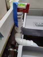
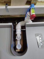
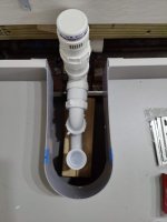
1) The AAV can be via a tubular connection under the sink, it just needs to be at least 4" above the horizontal fixture drain. There are various kits like this one to facilitate that: https://rectorseal.com/magic-trap-kit/ With separate lav drains, you' d need to do this for each lav. Thinking about it some more, the only real upside of separating the lav drains is to avoid the 3" pipe for the wet vent on the WC. Which is significant and probably worth it.

2) For the 1-1/2" lav fixture drain, with a trap adapter under the sink, you can remove the trap and use it for a cleanout. I'm a bit unclear on what if any cleanouts should exist on the 2" pipe. Obviously you can access the branch drain through the lav fixture drain, but a 2" cleanout would give better access. And your layout does have a lot of horizontal bends.

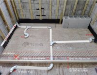
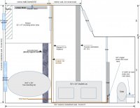
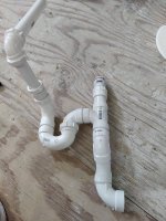
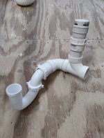
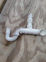
3) As to the picture, yes connectivity wise, but a few further tweaks/comments:

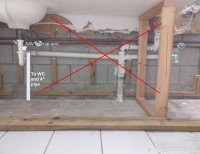
- The end where it says "to WC and 4" pipe", that needs to join in downstream of the WC and other lav. [If it joins upstream of the WC, now the WC wet vent is carrying over 4 DFUs, and there would need to be some 3" pipe.]

- On the shower trap arm, I'd be inclined to replace the combo with a wye that is farther towards the bottom of the picture, with a 45 at the appropriate point to the right of the current combo location. But if that complicates your platform framing too much, or raises your trap more than you'd like, what you show is fine.

- On the lav drain routing, I'd be inclined to minimize the distance up down the page from the upstream left-right lav drain segment to where the shower comes in. The tub can join the lav drain in a variety of ways as the lav drain run left right either above or below (on the page) the tub drain. The only constraint is that the lav drain shouldn't pass directly under the tub drain. Best I think would be to point the tub trap outlet at a 45 angle to the lav drain and run it directly into a wye on the lav drain.

Cheers, Wayne
 

Arnav

Member
Messages
150
Reaction score
10
Points
18
Location
Florida
Got it.

wwhitney said:
I'm confused as to why you are using the word ramp. Isn't there going to be a step? So it's a 2x6 platform?
Opps, yes. A platform. Not a ramp.

1. I am assuming I can use a regular 1.5" tee if I cannot get a hold of the trap kit.

2. Originally, the copper pipes for the shower valve were going around the perimeter exterior wall. I have since then removed them.
Do you see a reason why I can't route them within the 2 x 6 Platform by notching the top of the 2 x 6 joists?
Ideally they would be routed through the crawl space but it would be so much easier to work above the floor and just place them within the platform (pls see attached). Less ceiling to rip out below also.

3. Minor progress. I have added ball valves so that I can work on the copper pipes without having to inconvenience everyone.

I am off next week, so looking forward to get busy. I'll post a dry fitting of everything before I cement / sweat. I know PVC pipes can't be pushed all the way in to a fitting dry.

Thx!
 

Attachments

  • ball valves.jpg
    ball valves.jpg
    47.3 KB · Views: 110
  • copper routing.jpg
    copper routing.jpg
    65.2 KB · Views: 120

wwhitney

In the Trades
Messages
6,592
Reaction score
1,858
Points
113
Location
Berkeley, CA
1) Any reasonable undersink arrangement that puts the AAV 4" above the trap arm, and can be disassembled to allow access through the wall for snaking, should be fine.

2) You can notch the 2x6s for them, then I'd suggest nail plates over the notches (which I would then typically recess slightly so the top of the plate is flush). You could also drill the 2x6s, e.g. by just extending any row of holes to the face of the 2x6 riser so you can slide pipe in from the non-platform area.

Cheers, Wayne
 

Arnav

Member
Messages
150
Reaction score
10
Points
18
Location
Florida
Does this work connectivity wise for Lav 1?
- I have almost no room behind the floating vanity drawers
- I have no wall cavity to go into, just a 3" furred wall.
- The p-trap arm need to be around 10" (I don't have the sink yet to know exactly)
- Pls ignore the location of the supply lines in the pics. They are being moved.

Some of the more direct connectivity methods may barely work but provide less flexibility in the future or require the work to be more precise. Also, they would require making a notch in the ledger (two 2 x 6s) that holds the vanity which I am not sure if it will interfere with the atmospheric pressure for the AAV.
I tried both with a tubular p-trap as well as a solvent weld (the latter is much shorter).

Basically can I put a tubular 90 elbow before the p-trap?

The only down side is that since i am planning to use a p-trap with a nut (vs. a cemented one) the wall cavity will need to remain open which I am not sure if its against code. Maybe I can find a big 14" x 14" pvc outlet to put both the AAV and p-trap in.

What do you think?

Maybe they also make a tubular 90" pipe / elbow without nuts but haven't found any yet.

Thx!
 

Attachments

  • lav 1 drain 1.jpg
    lav 1 drain 1.jpg
    105.3 KB · Views: 113
  • lav 1 drain 2.jpg
    lav 1 drain 2.jpg
    74.4 KB · Views: 107

wwhitney

In the Trades
Messages
6,592
Reaction score
1,858
Points
113
Location
Berkeley, CA
- The geometry is allowable. [Possibly the piece between the trap outlet and the san-tee is too short, it may need to be 1" longer, the minimum horizontal distance the water should spill over coming out of the trap is twice the pipe diameter.]
- The AAV need to be accessible for changing out in the future.
- There's a preference here for everything under the counter to be tubular.
-What happens if you put the p-trap directly below the sink, as low as possible without interfering with the lower drawer? Can the AAV then be behind the sink, 4" above the trap arm, without hitting the counter?
- The bottom drawer could have a carve out in it for the p-trap, ending up with a "U"-shaped drawer. A pair of tubular 45s on the sink tailpiece could move the p-trap back to reduce the "perpendicular to the wall" dimension of the carve out.

Cheers, Wayne
 

Reach4

Well-Known Member
Messages
38,967
Reaction score
4,463
Points
113
Location
IL
Does this work connectivity wise for Lav 1?
You should have a tad more length between the santee and the glued trap. We discussed some p-trap issues to avoid crown vent. https://terrylove.com/forums/index.php?threads/adjusting-washer-standpipe-position.90807/ The table in post #7 dimension F shows the minimum for the cited parts. That is for a 2 inch glued trap.

The only down side is that since i am planning to use a p-trap with a nut (vs. a cemented one) the wall cavity will need to remain open which I am not sure if its against code.
You need access to an AAV to replace it. So if you have access to the AAV, wouldn't you also have access to a slip-joint trap? I am not sure what you are saying about the wall cavity.

Can you move the trap higher and avoid the drawers and have a place for the AAV before the drainage turns down? Maybe not, because you need that 4 inches under the AAV.
 

wwhitney

In the Trades
Messages
6,592
Reaction score
1,858
Points
113
Location
Berkeley, CA
Maybe not, because you need that 4 inches under the AAV.
I haven't seen any guidance on how the 4" requirement is measured. From trap arm inside bottom, center-line, or top? To top of threaded fitting that receives the AAV, or some point on the AAV (bottom, diaphragm, top)? Do you have a reference?

Cheers, Wayne
 

Arnav

Member
Messages
150
Reaction score
10
Points
18
Location
Florida
wwhitney said:
The geometry is allowable. [Possibly the piece between the trap outlet and the san-tee is too short, it may need to be 1" longer, the minimum horizontal distance the water should spill over coming out of the trap is twice the pipe diameter.]
Reach4 said:
You should have a tad more length between the santee and the glued trap.
Thanks for the info. I was not aware of this. I will make it longer. I have plenty of space to push the AAV to the side of the cabinet

wwhitney said:
What happens if you put the p-trap directly below the sink, as low as possible without interfering with the lower drawer? Can the AAV then be behind the sink, 4" above the trap arm, without hitting the counter?
Reach4 said:
Can you move the trap higher and avoid the drawers and have a place for the AAV before the drainage turns down? Maybe not, because you need that 4 inches under the AAV.
The issue is the length/depth of the p-trap arm not the height. Being a floating vanity, its depth is less than a regular vanity (19-1/2"). The vanity specifications are here: https://cdn.shopify.com/s/files/1/0262/9278/1109/files/VCONTE63WH-SPEC.pdf?v=1599466171
If I put a p-trap and an AAV all on the same straight arm I am passing the vanity's mid point where the drain is.

wwhitney said:
There's a preference here for everything under the counter to be tubular.
Interesting. I assumed the opposite since the tubular stuff seems so much more flimsily than the welded fittings.

wwhitney said:
The bottom drawer could have a carve out in it for the p-trap, ending up with a "U"-shaped drawer.
As mentioned above, the issue is the length / depth of the trap arm. While I cut all the other vanity cabinets in the house, I am hesitant to cut this one. The drawers seems to be providing an element of strength to it.

wwhitney said:
I haven't seen any guidance on how the 4" requirement is measured. From trap arm inside bottom, center-line, or top? To top of threaded fitting that receives the AAV, or some point on the AAV (bottom, diaphragm, top)?
I was wondering the same thing myself. For now, I measured from the top of the santee socket to the where the diaphragm is within the AAV.

Reach4 said:
I am not sure what you are saying about the wall cavity.
So normally, we hide the pipes in the wall. The p-trap can't fit in the space between the drawers and the wall so I need to leave a ~12" x ~12" section without drywall where the AAV and p-trap will reside. If they make them, perhaps you can use a metal or PVC outlet box to put both AAV and p-trap in (but I didn't find any yet).

Let me see what it looks like if I use all tubular stuff under the sink.

Granted i can avoid all this and just pull a pipe to place the AAV in the attic, but at the moment it seems more difficult.

BTW, i found an idiot proof way to explain how an AAV works. I can confirm that if you put an AAV to your lips and tilt your head buck, blowing out through it doesn't work. Breathing in does. You must do it with your head tilted fully back or else it doesn't work. :D
 

Attachments

  • vanity.jpg
    vanity.jpg
    62.8 KB · Views: 105

wwhitney

In the Trades
Messages
6,592
Reaction score
1,858
Points
113
Location
Berkeley, CA
The issue is the length/depth of the p-trap arm not the height. Being a floating vanity, its depth is less than a regular vanity (19-1/2"). The vanity specifications are here: https://cdn.shopify.com/s/files/1/0262/9278/1109/files/VCONTE63WH-SPEC.pdf?v=1599466171
If I put a p-trap and an AAV all on the same straight arm I am passing the vanity's mid point where the drain is.
I'm not sure I follow, as the term "depth" is a bit ambiguous here. Are you referring to the dimension perpendicular to the wall? If so, then I'm not clear on why the following wouldn't work: in a vertical configuration either inside the "wall" (furring), or just inside the cabinet, from top to bottom, drain, san-tee with trap adapter, short riser, female adapter, AAV (those all glued, except the threaded connection of the AAV; I assume the AAV has threads). Then in the dimension perpendicular to the wall, a short tubular trap arm and a tubular trap.

If the tubular parts are in line, then does that really stick out too far from the wall, past the sink drain? If so, is the space provided in the upper split drawer wide enough for you to have the u-bend of the trap oriented away from the wall, turned just enough from pointing directly away from the wall for the trap elbow to point straight at the wall but bypass the vertical tailpiece? So from the side, the tailpiece, u-bend, trap elbow, and trap arm would appear to overlap and make a loop.

Cheers, Wayne
 

Arnav

Member
Messages
150
Reaction score
10
Points
18
Location
Florida
Post 1 of 4 (I split the next few posts to make it easier to follow)

wwhitney said:
I'm not sure I follow, as the term "depth" is a bit ambiguous here. Are you referring to the dimension perpendicular to the wall?
Yes.

wwhitney said:
If so, then I'm not clear on why the following wouldn't work: in a vertical configuration either inside the "wall" (furring), or just inside the cabinet, from top to bottom, drain, san-tee with trap adapter, short riser, female adapter, AAV (those all glued, except the threaded connection of the AAV; I assume the AAV has threads). Then in the dimension perpendicular to the wall, a short tubular trap arm and a tubular trap.
Assuming I understood what you meant, then I tried it. There is not enough room behind the drawer to accommodate the AAV. Please see attached pics.
 

Attachments

  • tubular at ninty to aav 1.jpg
    tubular at ninty to aav 1.jpg
    86.5 KB · Views: 97
  • tubular at ninty to aav 2.jpg
    tubular at ninty to aav 2.jpg
    58.1 KB · Views: 95
  • tubular at ninty to aav 3.jpg
    tubular at ninty to aav 3.jpg
    58.9 KB · Views: 90
Last edited:

Arnav

Member
Messages
150
Reaction score
10
Points
18
Location
Florida
Post 2 of 4
wwhitney said:
If the tubular parts are in line, then does that really stick out too far from the wall, past the sink drain?
Disclaimer: The bath supplies place only delivered the vanity's cabinet but not the sink yet. I do remember the sink is at the midpoint of the vanity though. I'll try and go there tomorrow to measure their sample exactly.
For that configuration I am missing at least 1/4". It also wouldn't accommodate the slightly larger Otay AAVs if those are ever to be used. Please see attached pic. The black line on the blue tape is the midpoint of the sink. It also requires that the copper pipes be moved in front of the DWV but that is fine if needed.
 

Attachments

  • ptrap and aav inline 1.jpg
    ptrap and aav inline 1.jpg
    94.7 KB · Views: 105
  • ptrap and aav inline 2.jpg
    ptrap and aav inline 2.jpg
    50.9 KB · Views: 103
Last edited:

Arnav

Member
Messages
150
Reaction score
10
Points
18
Location
Florida
Post 3 / 4
wwhitney said:
If so, is the space provided in the upper split drawer wide enough for you to have the u-bend of the trap oriented away from the wall, turned just enough from pointing directly away from the wall for the trap elbow to point straight at the wall but bypass the vertical tailpiece? So from the side, the tailpiece, u-bend, trap elbow, and trap arm would appear to overlap and make a loop
If i understood what you meant, then I tried it as well. The space is wide enough but vertically it doesn't work
 

Attachments

  • p-trap u-turn.jpg
    p-trap u-turn.jpg
    48.3 KB · Views: 99
Last edited:

Arnav

Member
Messages
150
Reaction score
10
Points
18
Location
Florida

Attachments

  • union p-trap1.jpg
    union p-trap1.jpg
    65.6 KB · Views: 115
  • union p-trap2.jpg
    union p-trap2.jpg
    54.3 KB · Views: 97

wwhitney

In the Trades
Messages
6,592
Reaction score
1,858
Points
113
Location
Berkeley, CA
Apparently my description was lacking, as neither post 1 nor post 2 was what I was suggesting. The san-tee I mentioned was a san-tee in the usual orientation, with the openings at the top, bottom, and horizontal for the trap arm.

However, that suggestion was before I fully grokked the 2x6 ledger. Is that for supporting the countertop or what? If it's for the countertop, it would be fine to interrupt it for your plumbing, you'd just need to be sure each end of the channel you cut in it has support. E.g. directly to the concrete block, or the 3" of furring you mentioned. So it'd be like post #2, either with the san-tee as you have or as I originally proposed, with a wall box cut into the ledger and possibly that top rail of the vanity.

As to post 3, or post 2 if you don't want to cut into the ledger / top rail, have you considered getting another u-shaped drawer to use for the bottom drawer? Then you could lower the trap.

BTW, are you going to be install sheetrock between the furring and the vanity? That would be typical.

Cheers, Wayne
 
Top
Hey, wait a minute.

This is awkward, but...

It looks like you're using an ad blocker. We get it, but (1) terrylove.com can't live without ads, and (2) ad blockers can cause issues with videos and comments. If you'd like to support the site, please allow ads.

If any particular ad is your REASON for blocking ads, please let us know. We might be able to do something about it. Thanks.
I've Disabled AdBlock    No Thanks