Diagnosing a Well, Cistern and Pressure tank water system
Hello, A couple of quick question and then I will dump the mother load of my problems regarding my water system.
Fist, I am trying to figure out the functionality of the submersible well pump. My current understanding is that the Red wire gets a big jolt from a control box’s capacitor in order to start the motor of the pump.
Question(A): Does the Red wire continue to carry power after starting the motor?
Question(B): Does the common (Yellow) wire carry any power, and what does it do?
Question(C):The Black wire must be hot and what does it do?
Alright, here is how my problem started.
On a very cold night I left a faucet open and it trickled drops of water for six hours. Consequently something broke and now I don’t have any water.
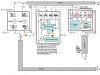
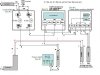
My water system is as follows(please see the 2 attachments. Pardon the directional arrows in the diagram because they might be misleading.):
1) A ¾ gal per minute, 60’ well, with a ½ hp pump. The only wire that is getting power is the yellow one and hence my three questions above.
2) A 1500 gal cistern with some floats and another ½ hp pump. All wires leading to it has power.
3) A Pressure tank with pressure switch. The raiser of the pressure switch was caked with solid mud and so I replaced it (I don’t know how it ever worked for the last 10 years). Both wires of the pressure switch has power. The pressure tank is not flooded. I did the knock from bottom to top test and it seems that it is ¾ empty.
4) There are 2 circuit breakers for the 2 pumps and the fuses are OK. I removed them and did continuity test. The circuit breaker#1 for the well pump has two 15amps fuses, and the circuit breaker#2 for the cistern pump has a 30amps and an 8amps fuse. Is this odd?
5) 240v main wire powers both circuit breakers.
6) The 15/15 amps circuit breaker feeds power to Pumptec-Plus (Pump protection system which in turn feeds power to Franklin Electric Control box (model 2801054915) which runs the well pump. One wire into Pumptec-plus had a constant 120v while the other wire got 120v when a switch inside the box was triggered manually. What is weired is that the 3 indicator light on the box showed no sign of life.
7) I assumed that the circuit board of the Pumptec-plus was busted and so I bypassed it (may be I made wrong connections) and substituted the same functionality(I was told) with a cheaper and smaller gadget(“231 Insider 230vâ€) that fit right inside Franklin Electric Control box (model 2801054915). I tested the power coming out of it and it only powered the yellow wire of the well pump. (That’s the reason for my first 3 questions A, B, and C.
8) Circuit Breaker # 2 with 30&8amps fuses powers a ‘Pumptec No Load Sensor’ pump protection system (model: 5800020116). Which in turn powers Franklin Electric Control box (model 2801054915). Two sets of wires comes out of it and heads toward the cistern. One conduit has RYB wires and the other has BW wires coming out of it. I tested all 5 wires at the junction box near the cistern and found that all of them carried 120v each.
9) Finally, one hot 120v wire coming out of Circuit Breaker#1 and one hot 120v wire coming out of ‘Pumptec No Load Sensor’ pump protection system feeds power to the pressure switch.
I am putting out so much detail only because I am totally confused and have no clue what is wrong with the system. I am hoping that some of you who are patiently reading this can point me in the right direction.
Any help will be much appreciated. Thanks.
Hello, A couple of quick question and then I will dump the mother load of my problems regarding my water system.
Fist, I am trying to figure out the functionality of the submersible well pump. My current understanding is that the Red wire gets a big jolt from a control box’s capacitor in order to start the motor of the pump.
Question(A): Does the Red wire continue to carry power after starting the motor?
Question(B): Does the common (Yellow) wire carry any power, and what does it do?
Question(C):The Black wire must be hot and what does it do?
Alright, here is how my problem started.
On a very cold night I left a faucet open and it trickled drops of water for six hours. Consequently something broke and now I don’t have any water.
My water system is as follows(please see the 2 attachments. Pardon the directional arrows in the diagram because they might be misleading.):
1) A ¾ gal per minute, 60’ well, with a ½ hp pump. The only wire that is getting power is the yellow one and hence my three questions above.
2) A 1500 gal cistern with some floats and another ½ hp pump. All wires leading to it has power.
3) A Pressure tank with pressure switch. The raiser of the pressure switch was caked with solid mud and so I replaced it (I don’t know how it ever worked for the last 10 years). Both wires of the pressure switch has power. The pressure tank is not flooded. I did the knock from bottom to top test and it seems that it is ¾ empty.
4) There are 2 circuit breakers for the 2 pumps and the fuses are OK. I removed them and did continuity test. The circuit breaker#1 for the well pump has two 15amps fuses, and the circuit breaker#2 for the cistern pump has a 30amps and an 8amps fuse. Is this odd?
5) 240v main wire powers both circuit breakers.
6) The 15/15 amps circuit breaker feeds power to Pumptec-Plus (Pump protection system which in turn feeds power to Franklin Electric Control box (model 2801054915) which runs the well pump. One wire into Pumptec-plus had a constant 120v while the other wire got 120v when a switch inside the box was triggered manually. What is weired is that the 3 indicator light on the box showed no sign of life.
7) I assumed that the circuit board of the Pumptec-plus was busted and so I bypassed it (may be I made wrong connections) and substituted the same functionality(I was told) with a cheaper and smaller gadget(“231 Insider 230vâ€) that fit right inside Franklin Electric Control box (model 2801054915). I tested the power coming out of it and it only powered the yellow wire of the well pump. (That’s the reason for my first 3 questions A, B, and C.
8) Circuit Breaker # 2 with 30&8amps fuses powers a ‘Pumptec No Load Sensor’ pump protection system (model: 5800020116). Which in turn powers Franklin Electric Control box (model 2801054915). Two sets of wires comes out of it and heads toward the cistern. One conduit has RYB wires and the other has BW wires coming out of it. I tested all 5 wires at the junction box near the cistern and found that all of them carried 120v each.
9) Finally, one hot 120v wire coming out of Circuit Breaker#1 and one hot 120v wire coming out of ‘Pumptec No Load Sensor’ pump protection system feeds power to the pressure switch.
I am putting out so much detail only because I am totally confused and have no clue what is wrong with the system. I am hoping that some of you who are patiently reading this can point me in the right direction.
Any help will be much appreciated. Thanks.