Draining & purging boiler system to add 3rd zone

Users who are viewing this thread

gtmtnbiker

New Member
Messages
30
Reaction score
0
Points
0
Location
Massachusetts
I will be starting a project to add a 3rd zone to my boiler. The plan is to split off the family room from the first floor zone to be a separate zone. It should have been a separate zone when the addition was built 30-40 years ago. The first floor is serviced by 1†pipe and is split into 2 loops. One loop is for the family room. The other loop is for the rest of the first floor (dining room, hallway, kitchen, and family room). The family room is at the very end of the loop. It’s also on the north side of the house and has an unheated basement. These factors make the room 3-4 degrees cooler than the rest of the house.

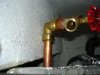
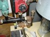
The question I have concerns draining & purging the boiler. In the first step of the project, I will be adding onto the supply manifold. I plan to shut the isolation valves (4) on the supply and return sides. I will also isolate the boiler water feed. I’ll open the boiler drain to drain water from the boiler and manifolds below the isolation valves. How does air get into the system to break the vacuum? Does one have to open the valve on top of the automatic air vent (see picture of supply manifold)?

I’ll add onto the supply manifold a 1 ¼†x ¾†reducing T, a plug, a nipple, and an isolation flange. At this point, I’ll pressurize the system with water to test for leaks. Then I’ll add the new circulator and the other isolation flange and do a second leak test.

On the return side, the previous plumber left no expansion capability. Unfortunately, the elbow on the manifold goes to the second floor zone so I will have to drain the whole system in order to get the elbow off. The plan was to cut into the copper above the isolation valve before disconnecting the valve, nipple, and elbow. I suppose that I could cut into the nipple with a sawzall but then I’ll have to use some sort of union when connecting it all back up again. The advantage of this approach would be that I wouldn’t have to drain the second floor zone. Still, I think I’m better off draining the entire system and cutting into the copper.

If I drain the entire system, how does air get into the system so that the water drains out? Is it through the automatic air vent again? Or do I need to open the manual bleeder valves on the slant-fin baseboard radiators?

When closing the system up again, I will purge most of the air from the system using the boiler drains on the return side. I will also go to each baseboard radiator and open the bleeder valves to purge any air.

Thanks for any assistance.
--Bill
 

Attachments

  • Front and side view of boiler.JPG
    Front and side view of boiler.JPG
    53.5 KB · Views: 3,880
  • Return manifold.JPG
    Return manifold.JPG
    40.7 KB · Views: 3,801
  • Front view of boiler.JPG
    Front view of boiler.JPG
    36.9 KB · Views: 3,828
  • Supply manifold.JPG
    Supply manifold.JPG
    37.7 KB · Views: 3,722

CHH

New Member
Messages
224
Reaction score
0
Points
0
Location
Denver, CO
Draining shouldn't be a big deal. Open the drain valve and if water doesn't come out then open a vent on a radiator and water will come out.

If you wanted to get creative then use air to blow the water out of the system. Be sure and keep the pressure low, less than 25 psi or so. The advantage to rigging up an air system is that you can use air to check for leaks before putting water in the system. It'll save a lot of mess. Don't ask how I know that.
 

GrumpyPlumber

Licensed Grump
Messages
1,521
Reaction score
57
Points
48
Location
Licensed Grump
I understand this is a DIY site, but there are certain things best left to experienced pro's to do.
Your about to dismantle a boiler and add a zone...lets start with a few questions.
Do you understand boiler circuitry, enough to confidently connect low voltage and house currents without burning the board?
Do you know what the operating temperature/pressure is?
Are you familiar with the safety features on the Weil McClain and how to ensure they work correctly?
Boilers can be very dangerous...break the wrong thing, or install the wrong valve and you have a potential bomb or CO hazard, it's in the news all the time.

Also...usually on a split zone a GOOD plumber will install valves so you can put resistance on one side of the split or the other to adjust the amount of hot water that flows into either one....look for those after the 1" breaks into the two 3/4".
You might have a solution already and not even know it.
 

gtmtnbiker

New Member
Messages
30
Reaction score
0
Points
0
Location
Massachusetts
Thanks for the response Grumpy.

In terms of electrical, I'm 100% confident in my skills having a EE background and done extensive wiring work on the house/car including swapping the Taco SR-501 to Taco SR-506 controller on my boiler. Adding the circulator from an electrical viewpoint will be easy.

I do appreciate the concern that boilers can be dangerous and you need to know what you're doing. My boiler has a temperature gauge and it should read between 160 & 180 deg. The pressure should be between 15-20 psi.

In terms of safety features, the boiler has:
1. spill switch - shuts down boiler if vent system becomes blocked (e.g, automatic damper does not open)
2. water temperature limit switch - shuts off gas valve if water temp exceeds its setting.
3. relief valve - if boiler exceeds certain pressure, it opens up relieving pressure

I have the CGA boiler manual and have read it several times. I will follow their documented checkout procedure before firing up the boiler.

You bring up a good point about balancing valves. I'm unable to determine if my system has them because the basement ceiling is plastered. I will have to crack it open to check. I was already planning to open the ceiling along the rim joists as part of the basement remodel so that they can be properly insulated.

--Bill
 

gtmtnbiker

New Member
Messages
30
Reaction score
0
Points
0
Location
Massachusetts
Thanks GHH,
What kind of valve would you put on to facilitate using air to blow on the system. I asked my supply house and the counter person didn't know of any device. I'm guessing that it would be some sort of shraeder valve. Would you use a test plug for this purpose?
 

Got_Nailed

DIY Senior Member
Messages
276
Reaction score
0
Points
0
Is this the question?
For adding air in to the system to glow out the lines and for a presser check?

See what size pipe you have where you want to attach in the compressor. Go to the compressor section and get the needed quick disconnect for you hose. Go to plumbing with the fitting and adapt it to the pipe fitting your going to tie into.
 

CHH

New Member
Messages
224
Reaction score
0
Points
0
Location
Denver, CO
I used a standard air quick-coupler. A Schrader valve should work fine too.

I don't have test plugs so just tested portions of the system as they were completed. My original installation had no isolation valves so I added those to each side (supply and return) of each zone and then added a couple valves on the main loop. I guess the original installer thought valves were too expensive or that draining the entire system just to replace a fitting was good practice.:)
 

gtmtnbiker

New Member
Messages
30
Reaction score
0
Points
0
Location
Massachusetts
Nailed & CHH, thanks for the advice on the fittings. I did see NPT 3/8" fittings in the air compressor section. I'll figure out some way to put a T, ball valve and the air compressor fitting to give me the ability to blow out the line.

Has anyone rigged something where you put a compressor fitting on a boiler drain? Something that you can easily attach and then remove when you're done? If so, what fittings did you use?
 

Jadnashua

Retired Defense Industry Engineer xxx
Messages
32,770
Reaction score
1,190
Points
113
Location
New England
Don't let the pressure get too high, there are various diaphram switches and things in a boiler that you could damage. You may want to isolate the boiler itself, then blow out the remaining lines.
 

CHH

New Member
Messages
224
Reaction score
0
Points
0
Location
Denver, CO
gtmtnbiker said:
Has anyone rigged something where you put a compressor fitting on a boiler drain? Something that you can easily attach and then remove when you're done? If so, what fittings did you use?

I used a female hose coupling to 1/2" NPT adapter I found at HD. I suspect that most hardware stores will have something similar in their brass fittings collection. The 1/2" was bushed down to 1/4" for the quick coupler and gauge. In hindsight it might have been better to use 1/2" everywhere but the gauge and quick-coupler themselves. I have a bad habit of snapping 1/4" off and it was tough to get the threads to seal on the 1/4" for the pressure tests.
 

GrumpyPlumber

Licensed Grump
Messages
1,521
Reaction score
57
Points
48
Location
Licensed Grump
Not sure why...but I'll assume you want to use the compressor to blow out the zones(?).
Flush them instead...open the draw-off on the return side with a garden hose attached and run outside, close the valve below it...then open the auto-feed...MUCH better than blowing it out with air, water will be much more effective than air at flushing out any sediment (If thats what your looking to do).
The systems circulators don't really put much "push" on the flow ...house pressure will.
 

gtmtnbiker

New Member
Messages
30
Reaction score
0
Points
0
Location
Massachusetts
The original idea was to ensure that the lines were completely free of water prior to sweating. I guess it's overkill. I probably should just drain the pipes and where I need to break the existing pipes to put new fittings, I should use a shop vac to suck out the water.

The other application will be for my father-in-law's summer house in VT. At the end of the season, we like to blow out the water lines in case the heat ever goes out. He currently uses some sort of mickey-mouse thing that he holds against the fitting by hand. I personally don't think it works too well. I would like to come up with a better fitting for him to use.

I was at the local hardware store and did see the air compressor fittings with 1/4" & 3/8" NPT that I could use. I'm sure that I can find the right combo of brass parts to fit my situation.
 

gtmtnbiker

New Member
Messages
30
Reaction score
0
Points
0
Location
Massachusetts
I'm progressing along nicely with this project. Tonight I added onto the supply manifold for the 3rd zone. I also added a little bit of copper.

Knock on wood but no leaks so far. The only tricky part was the 1 1/4 x 3/4 black reducing T. I got past 90 deg past vertical when it got real tough. It took a lot of effort to move it another 270 deg.

I attached a picture of what I've done so far. Feel free to point out any mistakes. I also attached a picture of my leak test apparatus. It's nothing more than a 90 deg Sharkbite fitting with a boiler drain attached to it. First I purge the air out of the line and then check for any leaks. I'm impressed with how easy it is to attach/detach the Sharkbite fitting. It's great for quick temporary repairs or for testing. I'll wait 5-10 years before I trust it for long-term use. Plus, I enjoy sweating pipes.
 

Attachments

  • Sharkbite fittings.JPG
    Sharkbite fittings.JPG
    65.9 KB · Views: 4,604
  • New zone - supply side.JPG
    New zone - supply side.JPG
    88.7 KB · Views: 3,725
Top
Hey, wait a minute.

This is awkward, but...

It looks like you're using an ad blocker. We get it, but (1) terrylove.com can't live without ads, and (2) ad blockers can cause issues with videos and comments. If you'd like to support the site, please allow ads.

If any particular ad is your REASON for blocking ads, please let us know. We might be able to do something about it. Thanks.
I've Disabled AdBlock    No Thanks