jackbombay
New Member
I built our house about 10 years ago and we recently built a garage with a 1 bedroom living space attached to the garage, here is how the well system is set up,
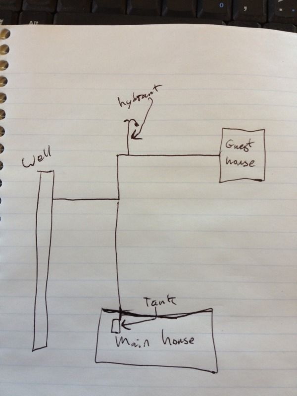
The well is 120 feet deep, the driller hit water at 55' feet, and the pump is a 2HP franklin pump set at 100', the pressure tank is in the house.
When the well pump turns on we get a notable drop in pressure followed by a notable spike in pressure, this only happens in the garage living space, here is a link to a youtube video of a pressure gauge on a hose bib when the well pump turns on, the pump kicks on at 48 PSI, I have the pressure turned up a bit to make sprinklers work better. I adjusted the air pressure in the pressure tank to 2 PSI less than the cut in pressure of the pump, I relieved all water pressure fro the tank before I adjusted the air pressure. The bladder in the tank is intact and functioning properly.
And here is a link to a video of when the well pump turns off.
Also, when another fixture is turned on and off the pressure swings pretty wildly, here is a link to a video of that, this shows the 2 hose bibs, one with a pressure gauge attached. NOTE:These hose bibs are fed from 2 totally different pipes, one is a hot water hose bib, filtered water running through an on demand water heater (that water first travels through our in floor heat tubing then through the heater, free 30 degree preheat in the summer) and the other hose bib is fed by unfiltered water, it is all obviously fed by our one well pump.
I also shot the same videos on a dual hose bib set up on the main house.
Here is a very similar dual hose bib set-up, these 2 hose bibs are also not fed from the same pipe, one is hooked up to a sprinkler timer and the other always has pressure available, both have a similar amount of 1/2" pex supplying water to them from righ next to the pressure tank. This is a video of when the well pump turns on. Here the pump kicks on at just over 50 PSI as this hose bib is about 7' lower than the one on the garage.
I didn't get a video of the well pump turning off as the pressure spike/drop is virtually identical to when the pump turns on, just at higher pressure of course.
And here is a video showing when one hose bib is turned on the pressure is only ever so slightly affected at the other hose bib, you can see right at the end of the video there is a just a 1-2 PSI bump in the gauge compared to the wild 10+ PSI swing in the garage under the same conditions.
And a little more info on the rest of the water system, the house has an 80 gallon bradford white combi-core water heater that provides domestic hot water and also heats the floors of the house, that in floor heat system is a closed system. The garage living space has a Noritz on demand water heater and also has in floor heat, but that is an open system, there is approximately 1,100 liner feet of 1/2" tubing in a 4" slab, by my calculations that is about 11 gallons of water. The water that feeds the water heater first travels through the in floor tubing, this takes the water from ~42* to ~70*, our well water is very cold, so the free ~30* temp rise for our hot water is significant.
What has me scratching my head is that for the pressure swings that accompany the open/closing of a fixture there must be something "elastic" is the system, such as trapped air, but there isn't, all lines/fixtures have had plenty of water run through them. The pressure tank in the house is the most elastic thing in the system but it doesn't cause any problems in the house so how does it in the garage which is 100' away from the pressure tank in the house?
I think that the water line to the garage should ideally have been run from the pressure tank in the house, but with how everything is built out, it would not be practical at this time to add such a line.
I imagine that this thread now has the possibility of turning into an open system/closed system debate, I'm open to hearing legitimate drawbacks to an open system, but I am currently primarily interested in information about my water hammer issue.
It would only take a half hour or so to temporarily eliminate the floor system from the domestic water system if anyone thinks doing so would provide valuable info to help solve this problem.
I did recently purchase a Cycle stop valve, due to the configuration of my system I need to install a CSV1W in the well itself, my plumber will be here on Thursday to try to figure out my water hammer issue, but it would be great to check out some possible solutions before he gets here.
Thanks for reading, if anyone has any ideas on how to fix this, I'm all ears.
")