Navicirc Woes on Navien 240A

Users who are viewing this thread

hardfacer

New Member
Messages
10
Reaction score
1
Points
3
Location
Rapid City,SD
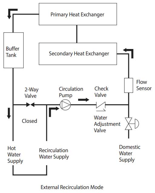
I have had the navicirc installed on my 240-A now for a couple years and it never really has worked like it should, for the most part we very rarely have warm or hot water at the kitchen sink. I've tried differant settings in the parameters to no avail, it still does not work right. I'm suspecting my lines are to small for the length of my run to get enough flow to run the burner. The lines are 1/2" with several 90's and is roughly 75-80' long. Right now for troubleshooting purposes I have P14 set to 5 min and P12 on 80 min. Dipswitch 1off 2ON 3off. Recirc valve set to EXT.
My question for the folks who are familiar with the 240A is with the recirc pump running what GPM are you seeing and what is the minimum flow required to fire the burner?
I can hear the pump running but I am NOT seeing any GPM's on the display when viewing them. I get about 1.5 GPM with the faucet open. The pump only runs for a min then shuts off. The unit does a good job of heating with the faucets open.
Any Thoughts?
 

Fitter30

Well-Known Member
Messages
4,373
Reaction score
800
Points
113
Location
Peace valley missouri
When has the heater been serviced and cleaned with vinegar. Flow meter isn't working not showing any flow. Here's a service.manual.
 

hardfacer

New Member
Messages
10
Reaction score
1
Points
3
Location
Rapid City,SD
I serviced the unit last year, shows flow from faucet use as I described but nothing when recirc pump is pumping.
 

Breplum

Licensed plumbing contractor
Messages
1,974
Reaction score
801
Points
113
Location
San Francisco Bay Area
Is the water piping outside the unit piped correctly? ext. check valve is required with exp tank on cold water supply pics?
PAR 1 oFF?
PAR 2 oN
Is PAR 17 set to Enable?
 

Bannerman

Well-Known Member
Messages
4,850
Reaction score
793
Points
113
Location
Ontario, Canada
See diagram below supports Breplum's comment regarding an external check valve just prior to the cold water inlet fitting.

The solenoid valve shown below, just prior to the recirculation return line fitting, is not required.


index.php
 

hardfacer

New Member
Messages
10
Reaction score
1
Points
3
Location
Rapid City,SD
Yes to all the questions here’s a pic of the connections. The connections are correct have not been able to post a picture, even a smaller size. Any help on posting pictures appreciated. The Cold water water supply has a tee back to the recirc. port with a check valve above the tee as pictured.
 
Last edited:

GReynolds929

Active Member
Messages
357
Reaction score
116
Points
43
Location
WA
Additionally the cold line has to be piped to the return port as shown. Otherwise the pump won't be able to circulate the water because of how the heater is plumbed internally. A picture of the unit and piping underneath would be very helpful.
 

Bannerman

Well-Known Member
Messages
4,850
Reaction score
793
Points
113
Location
Ontario, Canada
The Cold water water supply has a tee back to the recirc. port with a check valve above the tee as pictured.
The image above, shows the check valve permitting one way flow into the cold water supply port, not the recirculation return port. From the quoted statement, is not clear if your installation is configured correctly.

Imbedded images are to be 800 pixels or less. Larger images maybe hosted on an alternate site, and so only a link to the image will need to be imbedded in a comment.

The image below shows the internal flow path for the 240A, but does not show the additional check valve nor the common cold water supply connections to both the cold water supply port and the recirculation return port as is necessary when utilizing a NaviCirc or similar alternate brand of hybrid recirculation valve.

npe-recirc-flow-external.jpg
 
Last edited:

hardfacer

New Member
Messages
10
Reaction score
1
Points
3
Location
Rapid City,SD
The image above, shows the check valve permitting one way flow into the cold water supply port, not the recirculation return port. From the quoted statement, is not clear if your installation is configured correctly.

Imbedded images are to be 800 pixels or less. Larger images maybe hosted on an alternate site, and so only a link to the image will need to be imbedded in a comment.

The image below shows the internal flow path for the 240A, but does not show the additional check valve nor the common cold water supply connections to both the cold water supply port and the recirculation return port as is necessary when utilizing a NaviCirc or similar alternate brand of hybrid recirculation valve.

npe-recirc-flow-external.jpg
Bannerman I believe you have found my problem, I have the check valve WRONG. Will post back when installed correctly
 

Fitter30

Well-Known Member
Messages
4,373
Reaction score
800
Points
113
Location
Peace valley missouri
That pvc off the relief valve if it would ever let go for real less than a minute the pvc would be blown off but it wouldn't matter because the pump couldn't handle the volume of water anyway.
 

Bannerman

Well-Known Member
Messages
4,850
Reaction score
793
Points
113
Location
Ontario, Canada
After doing more research it appears that everything is piped correctly after all.

The check valve flow direction arrow is not visible in your photo. Suggest confirming the CV arrow is pointed upward, toward the WH inlet.

If the check valve is reversed, with the flow direction downward, then recirculation flow would follow a small loop from the internal pump, out through the CW supply inlet, over into the recirculation water supply port to the 3-way valve, and back to the pump inlet.
 

hardfacer

New Member
Messages
10
Reaction score
1
Points
3
Location
Rapid City,SD
The check valve flow direction arrow is not visible in your photo. Suggest confirming the CV arrow is pointed upward, toward the WH inlet.

If the check valve is reversed, with the flow direction downward, then recirculation flow would follow a small loop from the internal pump, out through the CW supply inlet, over into the recirculation water supply port to the 3-way valve, and back to the pump inlet.
In the scenario above if check valve was reversed and recirc valve off the water heater would not have a water suppy. I am sure flow direction is correct, the arrow is on the backside of the connection, I can't get a picture.
 

Bannerman

Well-Known Member
Messages
4,850
Reaction score
793
Points
113
Location
Ontario, Canada
if check valve was reversed and recirc valve off the water heater would not have a water suppy.
Review the flow path shown in the diagram in post #8. If the external check valve is installed in reverse, Cold water will continue to enter through the recirculation return port, but not the Domestic supply port.

I am sure flow direction is correct,
Don't assume the CV is installed correctly. Use a mirror to verify flow direction.
 

hardfacer

New Member
Messages
10
Reaction score
1
Points
3
Location
Rapid City,SD
Review the flow path shown in the diagram in post #8. If the external check valve is installed in reverse, Cold water will continue to enter through the recirculation return port, but not the Domestic supply port.


Don't assume the CV is installed correctly. Use a mirror to verify flow direction.
The Check Valve is a Water Source Brand, Unlike most check valves this one does not have an arrow. I completly understand how when the check is installed baclwards AND the recirc valve is open it will form a loop. As I stated above I closed the recirc valve, put all the settings back to to default for internal circulation. Water is being fed thru the check valve, from water supply into the water heater. Being a Pump operator for our Fire Department I understand flow paths for water. I still am convinced the navicirc is not letting the water thru as I originaly stated. Next time I'm at the hardware store I will get one in my hand to verify my statement
 

Bannerman

Well-Known Member
Messages
4,850
Reaction score
793
Points
113
Location
Ontario, Canada
Unlike most check valves this one does not have an arrow.
Look for an arrow directly cast into one end of one of the brass connectors.

The image below of an alternate Water Source CV model, shows a small, downward pointed arrow at the top of the valve.

water-source-pump-valves-cv75nl-64_1000.jpg
 
Top
Hey, wait a minute.

This is awkward, but...

It looks like you're using an ad blocker. We get it, but (1) terrylove.com can't live without ads, and (2) ad blockers can cause issues with videos and comments. If you'd like to support the site, please allow ads.

If any particular ad is your REASON for blocking ads, please let us know. We might be able to do something about it. Thanks.
I've Disabled AdBlock    No Thanks