Boiler Stuck On Standby

Users who are viewing this thread

FMcCracken

New Member
Messages
28
Reaction score
0
Points
1
Location
New York
Boiler was working this morning and for the past 8 years. Now the controller reads Standby. No other activity.

Primary Controller
Honeywell R7284 P1080 on STANDBY
Software Version 19
TT On, Limit Open, Cad Cell 999999 Ohms
Cad Cell
Last Cycle 426 Ohms
Last 10 Cycles 398 ohms
Baseline 165 ohms
Ignition time last 10 cycles 00:01
0 Lockouts since Baseline

Beckett AFG Series Oil Burner
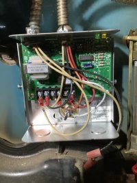
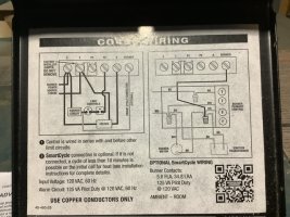
Low Water Cut-Off
Hydrolevel CycleGard CG450-1560

Steam heat.
Hot water on demand.
Neither steam nor HW demands are causing the boiler to ignite.

I replaced the Controller with same as existing.
Ohm-Checked transformer and it is working properly.
There is continuity between the red Burner wire in the LWCO and the red Limit wire in the Controller.

In order to get some heat in the house I change the settings of the controller to TT Open and Limit Closed, put a jumper on the TT terminals of the Controller, and connected the red Burner wire in the LWCO with the orange wire on the P2 terminal.

Burner ignited, ran 10 mins, shut down for a couple of minutes and then ignited again keeping this cycle going for 45 mins. Then the Pressure Relief Valve opened. Whoa !!! That’s an experience. Pressure was only 2.5 psi. Hence it was also replaced today.

I just replaced the LWCO with same. The existing unit’s probe was leaking. And wired it as originally wired. So, now that we have lots of brand new components it should fire right up. NOPE !!!

Any ideas?
 
Last edited:

Fitter30

Well-Known Member
Messages
4,371
Reaction score
800
Points
113
Location
Peace valley missouri
Standby there's no call for heat. Take a pic of the wiring diagram. Thermostat wires were on T&T3? relief valve opened at 2.5 lbs not close to 15 lbs never have I've seen a relief that far off unless the spring was broken in it. Here's the manual. Page 5 is wiring 6&7 installers setup. Cad cell has to under 1600 ohms.
 
Last edited:

FMcCracken

New Member
Messages
28
Reaction score
0
Points
1
Location
New York
Thank you for the reply. I have the same instructions. Came with the part. Here’s the rub. This boiler was performing very well for 8 years. I wired the new parts the same way as the original parts. I don’t understand why it fired up 4 days ago but won’t fire today.

Thermostat wires are wired to a transformer rather than the Controller. Don’t know or understand why but it did work.

Yeah, I understand that Standby means that there’s no call for heat, but the thermostat is set to 68* and the room is 60*. It used to trigger heat.
More info :
Thermostat wires (2) are wirenutted to the wire pair coming from the aquastat and go to a transformer - R and G terminals.
When I flip the burner emergency switch to provide power, the transformer clicks once, strong.
 

Fitter30

Well-Known Member
Messages
4,371
Reaction score
800
Points
113
Location
Peace valley missouri
More info :
Thermostat wires (2) are wirenutted to the wire pair coming from the aquastat and go to a transformer - R and G terminals.
When I flip the burner emergency switch to provide power, the transformer clicks once, strong.
Pull the cover off the low water control and take a pic. Transformers don't click might heat a circuit breaker trip in the transformer. Thermostat wires should go to far right last to terminals marked thermostat. Page4. 4,5or 6 diagrams
 
Last edited:

FMcCracken

New Member
Messages
28
Reaction score
0
Points
1
Location
New York
Loose wires are for the make-up water not hooked up. That’s next and shouldn’t impact this issue.
 

Attachments

  • IMG_0089.jpeg
    IMG_0089.jpeg
    97 KB · Views: 33

Fitter30

Well-Known Member
Messages
4,371
Reaction score
800
Points
113
Location
Peace valley missouri
Terminals from left to right 4 &6 marked as thermostat? Disconnect both tape the ends. With a meter power control.
1-2 120vac
1-3 0 vac
1-5 O vac
1-6. 0 vac
 

FMcCracken

New Member
Messages
28
Reaction score
0
Points
1
Location
New York
4 is marked as P2 for Burner circuit
6 is marked as Burner
 

Attachments

  • IMG_0090.jpeg
    IMG_0090.jpeg
    114.5 KB · Views: 35

Sylvan

Still learning
Messages
2,766
Reaction score
695
Points
113
Location
New York
" Pressure was only 2.5 psi"

Pressure read 2.5 PSI and Safety valve popped? How do you know the gauge is calibrated properly?
 

Fitter30

Well-Known Member
Messages
4,371
Reaction score
800
Points
113
Location
Peace valley missouri
Power off
Terminals left to right 1 to 6
Disconnect 4 and 6 tape ends
Power on
1-2 120vac
1-3. 0 vac
3 - case ground 0 vac
6- 1 0 vac
With ohm meter or continuity 3-6 0 ohms
Control have a test button push it 3-6 infinity
If terminals ring out hook the two disconnected up to 3 & 6
 

Fitter30

Well-Known Member
Messages
4,371
Reaction score
800
Points
113
Location
Peace valley missouri
The pic looks like it was removed even though it shows it wasn't supposed to be. With this control there is no separate 24 vac all terminals are 120vac. Where do the 4-&6 go to?
Which diagram is how its wired left or right?
 

Fitter30

Well-Known Member
Messages
4,371
Reaction score
800
Points
113
Location
Peace valley missouri
6 is powering 4
4-1 120vac & that same power has to power the burner and 1 at control should be neutral at burner
Neutral to case ground 0 vac
 

Fitter30

Well-Known Member
Messages
4,371
Reaction score
800
Points
113
Location
Peace valley missouri
When making multiple wiring changes and not drawing up a diagram or taking pictures - numbering the wires it easy to swap a couple of wires. Can't remember any job I've been on with a downed boiler that it was more than one control keeping it off . More controls might show up not working 100%. Steam traps not working part of the system problems. Time to have service person look at it. Post 1 TT jumpered, low water moved a wire. Later set boiler control to use TT. Sorry but dealing with a system need baby steps one item at a time and go down the list. Heatinghelp.com for a contractor in you area. Like to find out the outcome.
 
Top
Hey, wait a minute.

This is awkward, but...

It looks like you're using an ad blocker. We get it, but (1) terrylove.com can't live without ads, and (2) ad blockers can cause issues with videos and comments. If you'd like to support the site, please allow ads.

If any particular ad is your REASON for blocking ads, please let us know. We might be able to do something about it. Thanks.
I've Disabled AdBlock    No Thanks