Electrical Switch Problems?

Dmtm21

New Member
Messages
21
Reaction score
0
Points
0
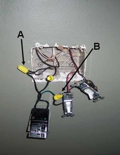
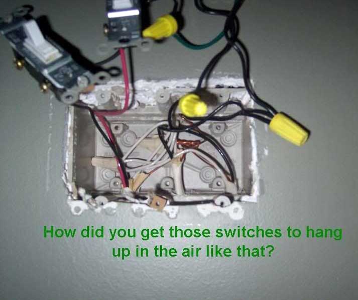
This will be a long winded message so I hope you can follow. I installed 2 new halogen can lights above my mantle this past weekend. I was able to get into the attic and wire them into an existing can light. In this room there is also a ceiling fan that has a switch for the light and a switch for the fan motor. Just so we are clear there is a electrical box on the wall with what seems to be three seperate switches, one for the ceiling fan light, one for the ceiling fan motor, and one for the existing single can light that I added 2 new can lights on. The problem I am having is that when I installed the dimmer switch on the single can light(now 3 can lights) place in the electrical box, I lost power to the other two switches that run the ceiling fan. I hope this makes some sense. I can try to attach a picture of the wall electrical box, if it would help. I have done installations like this before, so I feel like I know somewhat of what I am doing. Any help would be greatly appreciated. Thanks, Danny
 
I can't get the pictures to fit on this forum, too many jpgs. Please let me know if I can e-mail them to you.
 
upload your pictures there and then link them here so we all can see them.

if you have any problems let me know

or you can post the pic here like this

Burbon.jpg


And yes these are three of my horses.
 
Last edited by a moderator:
Sorry about that, I hope this helps.From left to right, new dimmer switch, ceiling fan light switch, ceiling fan motor switch. There are 3 switches in the box and 4 sets of wires, would the one coming out of the bottom be from an outlet? Thanks
 
Last edited by a moderator:
Have you changed any of the wires?

what you have is one two conductor cable feeding the box and one two conductor cable switching the old can and the three conductor cable switching the fan light.

find the one that is hot all the time and put pig tails on it so it can feed all three switches. there should be only three wire nuts in the box.
one connecting all the whites, one connecting all the grounds and one connecting one black to three pig tails that supply each of the switches.

the black in one of the two conductor cables is the switch leg for the cans and the black and red of the three conductor are switch legs for the fan and light.

Edit to add

good job using photo bucket but you need to back away from the switches a little and make sure that all the wires are pulled out straight next time
 
the green wire goes with the bare copper wires in the back of the box
 
Last edited by a moderator:
Take wire nut nut "A" losse and find the hot cable. this can be done be removing wire nut "B" and alternating the two blacks in the two conductor cables.

switch.jpg


Once you have the fan and light working put one wire from the dimmer under wire nut "B" and the other wire from the dimmer under the other black from the two conductor cable and your problem is sloved.

The Green goes with the bare conductors.


The bill is in the mail
 
Last edited by a moderator:
dmtm21 said:
Sorry about that, I hope this helps. From left to right, new dimmer switch, ceiling fan light switch, ceiling fan motor switch. There are 3 switches in the box and 4 sets of wires, would the one coming out of the bottom be from an outlet? Thanks


Where did you get to? I have been waiting to see if you got the problem solved yet.

Edited to add;
Still playing around with your pictures while I await your reply.

I am eagar to hear from you as what you have done thus far is dangerous and someone could get hurt if it is not installed correctly.
 

Attachments

  • side ways.JPG
    side ways.JPG
    18.2 KB · Views: 666
Last edited:
Sorry went to bed last night and missed all of your messages, I am going to try and fix it tonight when I get home from work. I can't thank you enough for your help, I'll let you know what happens tonight. Thanks again, Danny
 
Looks like he's trying to power the fan/light with the ground from the dimmer. One of the best ways a newcomer to the electrical game can spend $11, IMHO, is to buy a pocket hot-wire detector like the GVD-504A (http://www.amazon.com/GB-GVD-504A-Circuit-Non-Contact-Voltage/dp/B00004WLKP). Then it's easy to pick the hot wire out of the tangle, after un-nutting them all. Of course, if there are two, then it's a horse of a different color, like JW's.
 
Last edited:
You are the best JW, I really appreciate the help. You went to a lot to fix me up and I thank you. It works like a charm. Thanks again everyone and god bless.
 
dmtm21 said:
You are the best JW, I really appreciate the help. You went to a lot to fix me up and I thank you. It works like a charm. Thanks again everyone and god bless.


My heart is smiling and it was these words that caused it to happen.

Now email the owner of this site and tell him how much you appreciate him having this forum so you could get the help you needed.

Good luck in the future and if I can ever be of help don’t hesitate to give me a call.
 
I could be wrong, but from the looks of it, you have used the push-in holes on the back of the switch instead of using the screws. Some may disagree with me, but I think you should probally change that and use the screws. I have seen many instances where over time those wires will come loose and give you problems.
 
mattbee24 said:
I could be wrong, but from the looks of it, you have used the push-in holes on the back of the switch instead of using the screws. Some may disagree with me, but I think you should probally change that and use the screws. I have seen many instances where over time those wires will come loose and give you problems.

The only thing I have to say about that is- life is like a box of chocolates, you never know what you are going to get until you bite into it.

In 39 plus years I have never had a problem with the use to the push-in connections.

Old wives tales are nothing more than that, butts.

When done properly the push-in connection is as good as it gets.
 
I like backwiring (where the screws tighten clamps on the wires pushed in through the holes), but never use backstabbing (wires go into a spring clamp arrangement, screws aren't involved). Main reason is I use AWG12 for almost everything, but use mostly 15A outlets, which only allow AWG14 into their holes. Also, old wives' tale or not, I don't trust 'em. Not being a pro, my time is worth squat, so I can take the time to fuss with the screws. In any event, I like to turn in all the screws to minimize the risk of short circuits in metal boxes, no matter how I wire the device.
 
Not me, boy.

Now, where's that smiley with the hands over the mouth...?

Ah, after reading those excellent threads, I see I'm not the "Mike" frenchie referred to, so my conscience is clear. One last question, though... can anyone tell me the proper torque to tighten the screws to?
 
Last edited:
Back
Top